According to the US Energy Administration, about half of the world's energy is consumed by motors, so how to improve the energy consumption of motor control systems has become an important issue. To reduce the energy consumption of the motor, in addition to the energy efficiency design of the motor from the AC motor to the DC brushless motor (BLDC) and the motor body from IE1 to IE3, the most important thing is to have a cost-effective, high-performance, and completely for the motor Controlled dedicated microcontroller.
Advanced control algorithms are implemented with a dedicated high-performance microcontroller for motor control. The introduction of advanced control algorithms, in addition to allowing the system to achieve energy savings, also allows the entire control system to respond quickly and smoothly in response to load changes without sensors. Sensor configuration increases component and manufacturing costs, and in many cases it is impossible to place sensors, such as chemicals in the compressor and some products that cannot be placed because the space is too small. This article uses a 32-bit microcontroller to implement advanced field-oriented control (FOEL), high-frequency voltage injection technology and space vector PWM (SVPWM) control.
FOC
FOC is also called Vector Control. The original intention of FOC is to convert the control mode of AC motor into the control mode of DC motor. The control of DC motor is simple. Through the separate control of excitation current and torque current, The motor electromagnetic torque can be controlled simply and accurately.
Decoupling the magnetic field and torque of the induction motor: When the AC asynchronous motor is frequency-modulated, the voltage will change, the magnetic field will change, the frequency will not change when the voltage is regulated, and the magnetic field will change. Therefore, V/F is only a very rough control. The way the magnetic field does not reach the exact control of the magnetic field; the FOC can achieve relatively more accurate magnetic field control, but the FOC requires a higher computing power microcontroller. Figure 1 is a FOC system diagram based on Weiquan's 32-bit microcontroller. For each ADC interrupt in the inner loop, the following actions are taken:
· Using the Clarke transform, the phase current is converted from a static three-phase to a static two-phase current.
· Convert the static two-phase current into a dynamic two-phase current (rotary coordinate system) using the Park transformation.
· Calculate the speed and position of the motor using the sliding mode controller.
· Use the PI controller to control speed and current.
· Use the Park inverse transform to transform the dynamic two-phase current into a static two-phase current (stationary coordinate system).
· Transform the phase current from a static two-phase to a static three-phase current using the Clarke inverse transform.
· Update the PWM output duty cycle.
· The ADC interrupt is complete.
High frequency voltage injection estimation
The start of the motor is an important part of the PMSM control. The PMC's FOC system ensures a smooth start of the motor by applying a torque current perpendicular to the rotor's magnetic field, but this requires knowledge of the initial position of the motor. Most position sensorless controls do not predict the initial position of the rotor, typically starting with an open loop or positioning the motor to a predetermined position. Open-loop start-up is caused by different angles. The often-occurring conditions are reverse bias, jamton, etc., and the motor pre-positioning requirements are not applicable in many products.
For PMSM zero-speed/low-speed position sensorless control (Fig. 1), in order to solve the problem of inaccurate rotor position and speed estimation at low speed, it is generally adopted by Professors M. Corley and R. Lorenz of the University of Wisconsin, USA. The high-frequency signal injection method first proposed in 1996, the current research is more high-frequency voltage injection method. The method is based on the salient pole characteristics of the motor, injects a high-frequency voltage signal into the stator of the motor, and obtains rotor position information by performing specific signal processing (filtering, angle estimator) on the high-frequency current response.
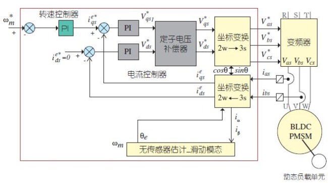
Figure 1: Schematic diagram of a magnetic field orientation/non-sensing control system based on WT58F032
According to the different voltage injection methods, the high-frequency voltage injection method can be divided into the following two categories: (1) Rotating high-frequency voltage injection method - injecting a rotating high-frequency voltage signal into the stator coordinate system, the negative sequence component of the high-frequency current response The rotor position information is included; the motor rotor position is obtained by demodulating the signal. (2) Pulsating high-frequency voltage injection method--Injecting a pulsating high-frequency voltage signal in the estimated rotating coordinate system, the high-frequency component of the current response will contain a position estimation error; by processing the high-frequency current signal, the estimated position is made Converging to the actual location.
Space vector pulse width modulation
The space vector PWM (SVPWM) works by synthesizing the stator current of the motor via a PWM modulated voltage vector using three sets of half-bridge inverters. The resultant magnetic flux vector generated on the stator coil interacts with the rotor flux to generate torque that causes the motor to rotate. SVPWM is based on the composite stator flux vector to determine the switching timing of the three sets of half-bridge inverters, so it is named space vector pulse width modulation. This modulation method is to control the voltage vector so that the motor air gap rotating flux vector trajectory approaches an ideal circle with minimal flux fluctuations and the lowest torque ripple (Torque Ripple), so in the case of open circuit control, Motor speed fluctuations are also minimal. Table 1 shows the three sets of half-bridge inverter power switching devices of the motor drive circuit. Because the space vector pulse width modulation switch control has no definition of simultaneous switching of the up and down switches, it can be regarded as two state switch timings (upper switch). OFF, the lower switch is ON, or the upper switch is ON and the lower switch is OFF). Therefore, a total of eight switch state combinations can be produced for three sets of power switching devices.
Replace the old cigarette drip tip, the service life is longer, and the good air filter function of the cigarette holder can make your electronic cigarette
taste better and experience better.
We are China leading manufacturer and supplier of Disposable Vapes puff bars, disposable vape drip tip,e-cigarette drip tip dust cap,
e-cigarette drip tip adapter, and e-cigarette kit, and we specialize in disposable vapes, e-cigarette vape pens, e-cigarette kits, etc.
disposable vape drip tip,e-cigarette drip tip dust cap,e-cigarette drip tip adapter,e cig drip tip filter,e-cigarette drip tip dust cover
Ningbo Autrends International Trade Co.,Ltd. , https://www.ecigarettevapepods.com