Low ripple, high precision current source is an important instrument and equipment; widely used in electric light source, electrochemistry, communication, measurement technology, electronic instruments and other fields. At present, the current source on the market does not have a continuously adjustable function; and the output current range is small, the precision is low, the ripple is large, and the price is expensive; in order to cope with the market demand; the output current is designed to be 0~5A; the maximum power is 100W. High-precision programmable current source; main technical indicators are: current source operating voltage 220V/50Hz; output current range 0~5A continuously adjustable; line adjustment rate "0. 05% + 0. 1MA; load adjustment rate "0. 05% +1MA The accuracy is ≪0. 05%+2MA; the readback accuracy is “0. 05%+2MA; the system setting resolution is 0. 1MA; the readback resolution is 0. 01MA.
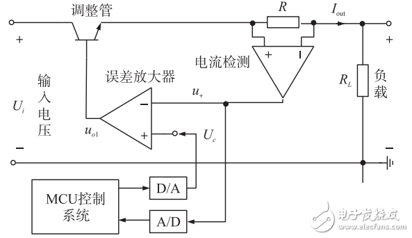
1, linear steady flow principleThe structure of the digital linear current-stabilizing circuit is shown in Figure 1. It consists of an adjustment tube, an error amplifier, a current detector, a D/A, an A/D, and an MCU control system. When the adjustment tube works in the amplified state, the tube voltage potential is controlled by the adjustment tube to control the tube pressure drop UCE. In order to stabilize the output current, when the load changes or the input voltage UI fluctuates, the UCE needs to be adjusted to keep the output current. constant. The current detection and error amplifier are used to form a negative feedback circuit structure to achieve the steady current target. Assume that the UI or RL increases, the output current increases, and the output voltage U+ of the current detection circuit increases. If the control voltage UC remains unchanged, the error amplifier outputs U0l. Decrease, the tube pressure drop UCE of the adjustment tube rises, so that the output current remains unchanged. Set the current detection circuit voltage amplification factor to K, which is obtained by the virtual short and virtual break characteristics of the operational amplifier:
U+=KRI=Uc(1)
Thus, I = UC / KR. Therefore, the circuit can achieve the purpose of steady current. As can be seen from the equation (1), the magnitude of the output current can be changed by changing the magnitude of the control voltage UC. The MCU system can achieve output power flow control through D/A devices.

Figure 1 Principle of linear steady current circuit
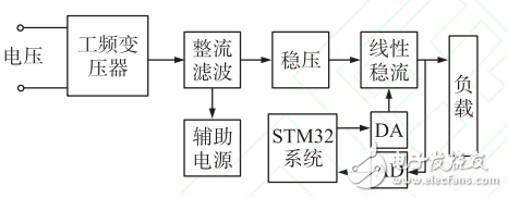
2, current source hardware designThe hardware block diagram of the current source is shown in Figure 2. It consists of a T-frequency transformer, single-phase bridge rectifier filtering, primary regulation, linear steady current, auxiliary power supply, STM32 system, D/A and A/D. The auxiliary power supply uses LM317, LM337, LM7805, LM7905, AMS1117 power management chip to provide the normal working voltage of the chip in the circuit. The STM32 MCU system controls the linear steady current output through D/A, and reads the output value through A/D to achieve the program control purpose.

Figure 2 STM32 based current source hardware block diagram
German type cable reel Non-rewirable, 230V~, IP20, Class I, with a thermal cut-out, with a non-rewirable plug with cord H05VV-F 3G1,0-1,5mm 2 ,
with 4-way socket outlet with or without shutters.
Germany Cable Reel,Cable Reel,Automatic Cable Reel,Cable Spool Reel
CIXI KYFEN ELECTRONICS CO.,LTD, , https://www.kyfengroup.com