As an essential process for modern manufacturing, welding has always played an important role in the field of material processing. Welding is a complex process involving arc physics, heat transfer, metallurgy, and mechanics. It involves the heat transfer process, melting and solidification of metals, phase change during cooling, welding stress and deformation, etc. And designers are concerned with the key issues. The welding stress and deformation generated during the welding process not only affect the manufacturing process of the welded structure, but also affect the performance of the welded structure. These defects are mainly caused by unreasonable thermal processes during welding. Due to the concentrated instantaneous heat input of high energy, considerable residual stress and deformation will occur during and after welding, affecting the processing accuracy and dimensional stability of the structure. Therefore, it is of great significance for the quantitative analysis and prediction of the stress field at the welding temperature.
The traditional welding temperature field and stress test rely on the designer's experience or a semi-empirical formula based on statistical basis, but such methods have obvious limitations, and the new process cannot predictively predict, resulting in drastic experimental costs. As a result, the use of numerical simulations for welding represents a great advantage.
ANSYS, as the world-famous universal structural analysis software, provides complete analysis functions and complete material constitutive relations, providing technical assurance for welding simulation. In this paper, ANSYS is used as a platform to explain the welding temperature field simulation and the basic theory and simulation flow of thermal deformation and stress simulation, which provides a certain reference for the enterprise designers.
2 Theoretical Basis of Welding Numerical SimulationThe temperature field and stress deformation in the welding problem can finally be attributed to solving the differential equations. The solution to this type of equation is usually two major categories: analytical method and numerical method. Since only a large number of simplifying assumptions are made and the problem is relatively simple, it is possible to obtain an equation solution using the analytical method. Therefore, numerical methods are often used for the simulation of welding problems. In welding analysis, commonly used numerical methods include: difference method, finite element method, numerical integration method, Monte Carlo method.
Difference method: The difference method solves by converting the differential equation into a difference equation. For the geometrical characteristics of the rule and the uniform material properties, the programming is simple and the convergence is good. However, this method is often limited to the regular differential meshes (squares, rectangles, triangles, etc.). At the same time, the difference method only considers the role of the nodes, and does not consider the contribution of the internodes. It is often used to perform problems such as welding heat conduction and hydrogen diffusion. Research.
Finite Element Method: The finite element method transforms a continuum into a discrete model consisting of a finite number of elements, and solves the numerical solution of the discrete model through a displacement function. This method is flexible and has a wide range of applications. Therefore, it is widely used in welding heat transfer, welding thermal elastoplastic stress, deformation and fracture analysis of welded structures.
Numerical integration method: This method uses Simpson's rule to solve the problem that it is difficult to obtain the original function. Through this method, the problem of solving the complex original function is avoided, and at the same time, using less points can obtain higher accuracy.
Monte Carlo method: This method is based on stochastic simulation techniques and carries out a numerical simulation of the problem of random processes.
Welding simulation is usually based on the above theory to simulate the heat conduction, thermal elastoplastic stress and other issues, but the reasonable choice of heat source function and calculate the post-weld stress and other issues require the designer to select the appropriate mathematical model.
2.1 Welding Numerical Simulation Common Heat Source Model
Welding heat process is one of the main factors affecting the quality and productivity of welding. Therefore, the accurate simulation of welding heat process is the premise of accurate analysis of welding stress and deformation. In the early stage of the analysis of welding thermal processes, many previous theoretical researches have been done and a variety of heat source distribution models have been proposed:
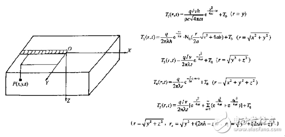
Concentrated heat source: Rosenthai-Rykalin formula
As a typical analytical method, the method considers that the heat source is concentrated at one point. This method is only suitable when the study area is far away from the heat source. At the same time, this method cannot describe the distribution law of the heat source, and has a great influence on the fusion zone and the heat affected zone.
Planar heat source: Gaussian heat source, double elliptical heat source
Gaussian heat source
The Gaussian heat source distribution assumes that the welding heat source has a symmetrical distribution characteristic. In low-speed welding, the effect is good. When the welding speed is high, the heat source is no longer symmetrically distributed, and the error is large. This method is suitable for situations where the arc stiffness is weak and the arc has less impact on the bath.
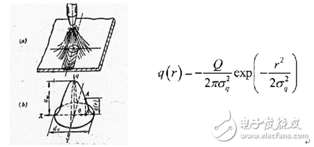
Although the Gaussian distribution gives the heat source distribution, it does not consider the influence of welding torch movement on the heat source distribution. In fact, because of the difference in the speed of heating and cooling of the weld, the heating area in front of the arc is smaller than the heating area in the rear.
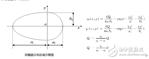
Bi-elliptical heat source
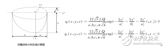
Volume distribution heat source: semi-ellipsoid heat source, double ellipsoid heat source
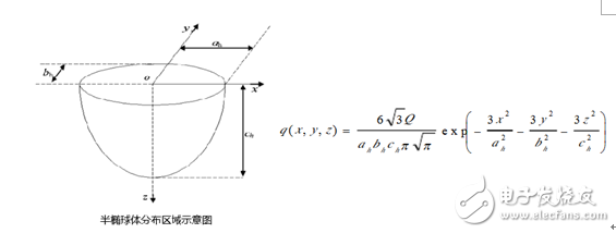
Semi-ellipsoid heat source
For gas metal arc welding or high energy beam welding, the heat flux of the welding heat source not only acts on the surface of the workpiece, but also acts in the direction of the thickness of the workpiece. At this point, the welding heat source should be used as a heat source for volume distribution. In order to consider the distribution of the arc heat flow along the thickness of the workpiece, the ellipsoidal mode can be used to describe
In fact, due to the movement of the arc in the welding direction, the arc heat flow is asymmetrically distributed. Due to the influence of welding speed, the heating area in front of the arc is smaller than that behind the arc; the heating area is not a single semi-ellipsoid that is symmetrical about the center line of the arc, but a double half ellipsoid, and the front and rear semi-ellipsoidal shapes of the arc Not the same
Double ellipsoid heat source
2.2 Welding deformation simulation common method
The dynamic stress-strain process resulting from welding and its subsequent residual stress and residual deformation are important factors leading to weld cracking and joint strength and performance degradation. Therefore, the following theories have been developed for the calculation of weld deformation and residual stress:
Analytic method: One-dimensional residual plastic deformation analysis
This method is based on the theory of welding deformation and determines the relationship between the longitudinal plastic deformation of welding joints and the welding process parameters and welding conditions. It requires a lot of experience to accumulate. This method is more suitable for regular beam structures with uniform cross-sections.
Intrinsic strain method: Inherent strain can be seen as a source of residual stress
Intrinsic strain during welding includes plastic strain, temperature strain and phase change strain. After a welding heat cycle of the welded component, the temperature strain is zero, and the intrinsic strain is the sum of the plastic strain and the phase change strain residual. During welding, intrinsic strain exists in the weld and its vicinity. Therefore, understanding the distribution law of intrinsic strain can use only one elastic finite element calculation to predict the magnitude of residual stress and structural deformation, but this method also focuses on deformation of the structure after welding. Approximate method, without considering the entire welding heat transfer process
Thermal elasto-plastic finite element method: recording welding heat transfer process, describing stress and deformation of dynamic process
The thermal elasto-plastic finite element method first analyzes the welding heat process, and obtains the transient temperature field of the welded structure. The results are then used to calculate the welding stress and deformation. Because this calculation is a non-linear calculation process, it requires a large amount of calculation and is generally used to study the mechanical behavior of welded joints, but not for the overall study of large-scale complex structures.
3 welding simulation case3.1 Welding Simulation Based on ANSYS Workbench Platform
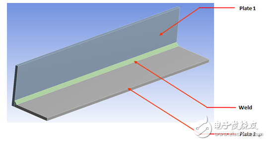
Laser welding was used for the following components. The ANSYS Workbench was used as a platform to simulate temperature field changes and stress field changes of the model.
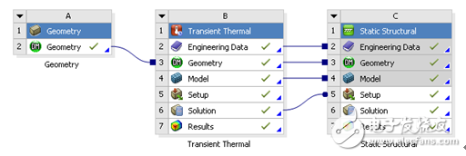
ANSYS Workbench serves as a unified multi-field coupling analysis platform that supports data collaboration. Therefore, this welding analysis coupling project is created in the Workbench, as shown in the following figure.
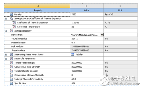
In this example, only the welding simulation process is taken as an example. Therefore, the material is assumed to be a linear elastic structural steel. The input material parameters in the EngineerData are as follows:
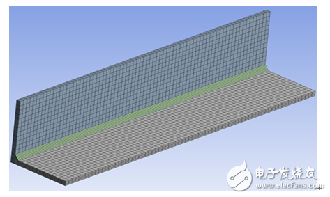
ANSYS Workbench uses ANSYS Meshing as a basis for meshing the model. For the two weldments and welds in this model, the two welds are divided by hexahedron. In addition, the software also provides a lot of size funcTIon, local control, etc. Function, high-quality meshing for geometric models of different features.
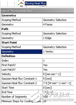
Transient thermal analysis of the welding process with the Workbench platform requires the use of the Moving_Heat_Flux plug-in developed from ANSYS Workbench. The plug-in is embedded in the Workbench interface and provides a mobile heat source distribution method based on the planar Gaussian heat source method. In this plug-in, the user can specify welding torch speed, welding current, power, and welding time. In addition, the analysis of the heat transfer process requires the input of other boundary conditions such as ConvecTIon required for transient thermal analysis. The welding-related parameters entered in this case are as follows:
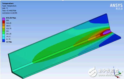
For such large-scale simulation problems, it is recommended to use HPC high-performance computing, which can give full play to the computer hardware performance and greatly improve the solution efficiency. The final thermal transient analysis results for this parameter are as follows:
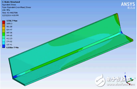
Based on transient thermal analysis, post-weld stress analysis can be performed. Through the coupled analysis flow of the ANSYS Workbench established above, the thermal analysis temperature field is transmitted to the structure field through the import load method for stress analysis.
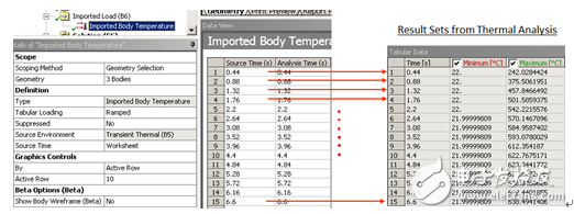
At the same time, according to the actual conditions, the members are subjected to constraints and stress analysis. Finally, the stress cloud diagram at a certain moment is as follows:
3.2 Welding Simulation Based on ANSYS Classic Interface
As mentioned earlier, there are many limitations when using the Workbench as a platform for welding simulation. For example, other types of heat source models cannot be selected. Therefore, the user can perform welding simulation based on the ANSYS classic version. The welding simulation based on the ANSYS classic version can be performed in the command flow mode, and the welding parameters can be read in as a parameter, which is very convenient for optimizing the welding analysis.
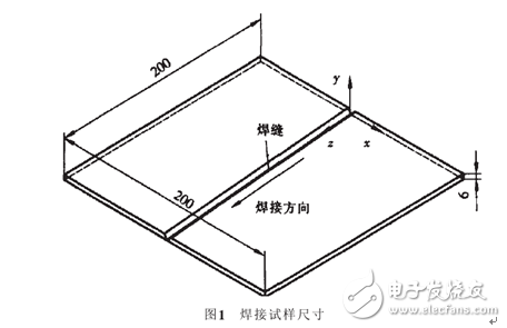
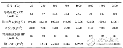
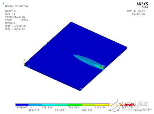
In this example, the simulation of the welding temperature field uses a weld plate size of 200mmX200mmX6mm, and the sample material is Q235A. The material parameters are shown in the following table. In order to ensure penetration, two steel plates open a 45° groove. The welding method uses arc welding. The welding parameters are: welding current 180A, arc voltage 20V, welding speed 4.8mm/s, welding heat input 0.75kJ/mm, welding efficiency η=0.825, structure and air heat transfer coefficient 15W/( m^2*°C).
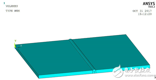
The geometric model of this component is established in the classic version of ANSYS. Using solid70, the established model is shown in the following figure:
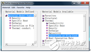
Create a complete material parameter table through the MP command, as shown in the following figure:
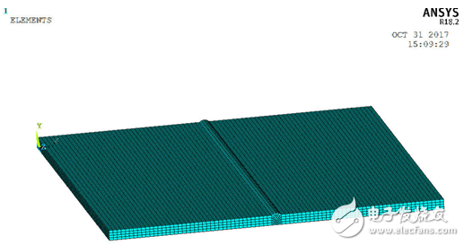
Through esize and other commands, local grid control of the model is performed to generate a hexahedral mesh and high mesh quality is achieved. The finite element model is as follows:
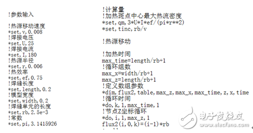
In this example, Gaussian heat source is also used for simulation. The relevant welding process is expressed in terms of parameters, which provides the basis for later optimization. The typical command flow is as follows:
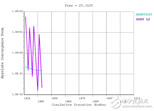
A fixed constraint is applied to the bottom of the model, and iterative calculations are performed according to the solution parameters set in the APDL. The iterative curve is as follows:
After the solution calculation, the temperature field distribution cloud diagram of the welding part can be obtained, and the temperature field distribution cloud diagram at a certain moment as presented in the following figure:
Through the above introduction, based on the ANSYS software, the temperature field and stress field of the welding process can be easily simulated. At present, only the welding simulation in the form of plug-in is supported in the Workbench, and only the heat source distribution mode of the planar Gaussian heat source can be considered. Considering other methods of heat source, APDL programming needs to be based on the ANSYS Classic Edition. In addition, the user can also use the life and death unit to carry out welding simulation. It should be noted that the way of life and death is through the control unit. The way to simulate the weld filling process can be used to simulate a relatively complex heat input situation. Since the heat source distribution and the life and death unit are two different calculation methods, they cannot be used together.
ANSYS software provides a powerful technical guarantee for welding simulation through a complete material constitutive relationship and solving ability. Therefore, designers can use this as a welding simulation to provide a reference for the setting of current, voltage, and other welding process parameters. Optimize the welding process.
Solder Series Centronic Connector
Solder Series Centronic Connector
Current Rating:5A
Dielectric Withstanding Voltage:1000V for one minute
Insulation Resistance:1000MΩ Min.(at 500V DC)
Contact Resistance:35mΩ Max.
Temperature:-55°C to +105°C
Solder Series Centronic Connector
ShenZhen Antenk Electronics Co,Ltd , https://www.pcbsocket.com