As a new-generation industrial control device, PLC is widely used in various industrial fields such as logic control and sequence control. Its rich command system makes it play a big role in various control systems. This article takes the lantern control system as an example to introduce shifting and The shift register instruction is applied, and the usage and difference of the three are summarized by comparing different control effects.
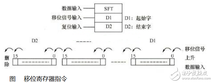
The shift register instruction SFT is similar to a serial shift register. On the rising edge of the shift signal, the SFT instruction sequentially shifts the data of the word participating in the shift to the upper bit by one bit, the value of the highest bit overflows, and the data input signal is collected to place it at the lowest bit. Its ladder symbol is shown in the figure.
The operand area is:
D1 is the start word, and its range is CIO, WR, HR, AR (448 to 959).
D2 is the end word, and its range is CIO, WR, HR, and AR (448 to 959).
The SFT instruction requires that the words participating in the shift must be of the same type. The shift register includes all words between the start word and the end word, and the address of the end word should be greater than or equal to the address of the start word. When the reset terminal is ON, the data of all shift registers will be cleared.
The programmable logic controller (PLC) is a new generation industrial control device based on automatic control technology, microcomputer technology and communication technology. PLC is widely used in logic control, sequence control and so on. PLC has a rich instruction system, including basic instructions, function instructions and advanced instructions. This paper takes the lantern control system as an example to introduce the application of logic shift, cyclic shift and shift register instructions.
Logical shift instruction applicationThe logical shift instruction includes two types of left shift and right shift. The shift data type includes three types of byte, word and double word. This paper introduces its application by taking the byte logical left shift instruction (SLB) as an example. The ladder diagram and statement table of SLB are shown in Figure 1. Its function is to shift the data input from the IN terminal to the left by N bits when EN is valid, and the result is output to the OUT memory location. The shift bit automatically fills 0, and the last shift bit is saved in SM1.1. When the result in the memory cell is 0, SM1.0 is 1. The ladder diagram of the lantern control system designed with the SLB instruction is shown in Figure 2.
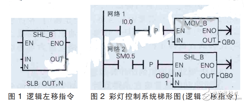
Program analysis: After the switch is closed, the data 1 is first transmitted to QB0. At this time, the first group of lights is lit, and then the next group of lights is turned on every 1s. When the eighth group of lights is lit, the lantern system stop working. It can be seen that for the SLB instruction, the highest bit overflows and the lowest bit complements 0, so the maximum number of shifts is 8, and it cannot be cycled.
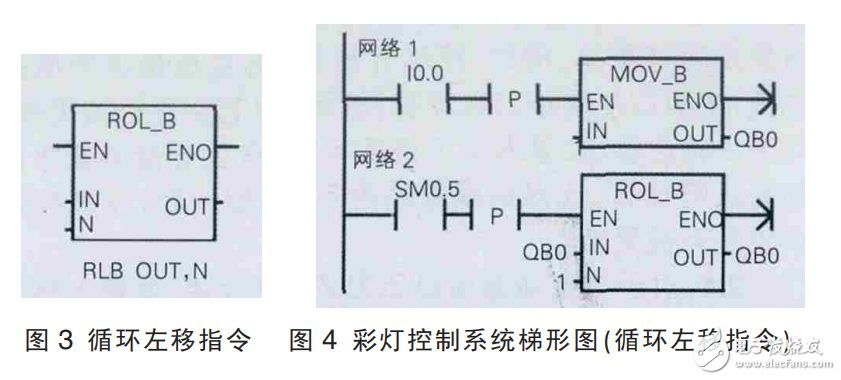
Rotation shift instruction applicationThe cyclic shift instruction also includes two types of left shift and right shift. The shift data type includes three types of byte, word and double word. This paper introduces its application by taking the byte cyclic left shift instruction (RLB) as an example. The ladder diagram and statement list of the RLB instruction are shown in Figure 3. The function is to shift the byte data input from the IN terminal to the left by N bits when EN is valid, and the result is output to the OUT memory location. The last shift bit is saved in SM1.1, and SM1.0 is 1 when the result in the memory location is 0. The ladder diagram of the lantern control system designed with the RLB instruction is shown in Figure 4.
Program analysis: After the switch is closed, the data 1 is first transmitted to QB0. At this time, the first group of lights is lit, and then the next set of lights is illuminated in sequence every 1s. When the eighth group of lights is lit, the lantern system Loop work. It can be seen that for the RLB instruction due to its high displacement to low position and low displacement to high position, the actual number of shifts is the result of the remainder of 8 and can be cycled.
The shift register instruction (SHRB) can implement the left shift and the right shift function, and the shift data type is bit. This article introduces its application by taking the left shift case as an example. The ladder diagram and statement table of the SHRB instruction are shown in Figure 5. The function is to shift the value of the input DATA sample into the shift register when EN is valid, and move the entire shift register by one bit. S_BIT specifies the lowest bit of the shift register, N specifies the length of the shift register and the shift direction, N>0 shifts to the left, N“0 shifts to the right, and the maximum value of N is 64. The shift-out bit is stored in SM1.1, and SM1.0 is 1 when the result in the shift register is 0. The ladder diagram of the lantern control system designed with the SHRB instruction is shown in Figure 6.
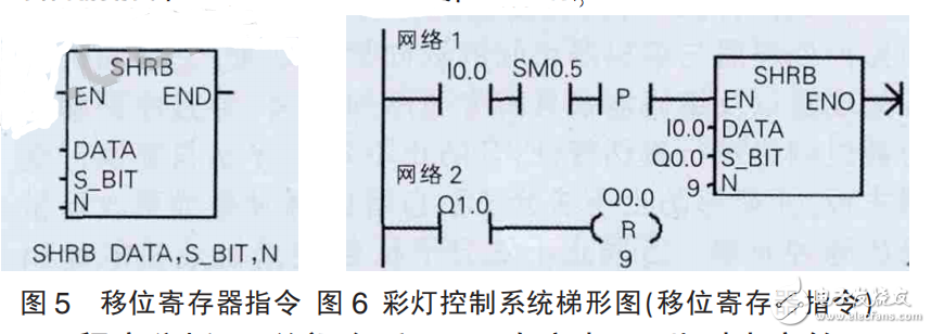
Program analysis: After the switch is closed, Q0.0 is high level. At this time, the first group of lights is lit, and then the next group of lights is illuminated every 1s. When the eighth group lights are lit, the lantern system Loop work. It can be seen that for the shift register instruction, since the data of the lowest bit S_BIT bit is determined by DATA and the other bits are shifted to the left in turn, it is necessary to reset the loop operation.
The different effects of the lantern control implemented by the logic shift, cyclic shift and shift register instructions show that the three differences are as follows:
Same point:
1 can realize left shift and right shift function;
2 After the shift, the flag is affected;
3 The enable terminals are all valid on the rising edge.
difference:1 The logical shift instruction and the cyclic shift instruction are 2 data ends, and the shift register instruction is 3 data ends;
2 The shift data type of the logical shift instruction and the cyclic shift instruction may be a byte, a word or a double word, and the shift register instruction shift data type is a bit;
The N value of the 3 logic shift instruction is greater than 0, and is affected by the initial value of the IN terminal. The N of the cyclic shift instruction is greater than 0, and the actual shift count is the result of the remainder of the data type. The N of the shift register instruction may be greater than 0, can also be less than 0, and its maximum value is 64;
4 The logic shift instruction cannot implement the loop function, and the cyclic shift instruction and the shift register instruction can implement the loop function.
Fiber Optic Patch Panel,Fiber Patch Panel,Fiber Distribution Panel,Optical Patch Panel
Cixi Dani Plastic Products Co.,Ltd , https://www.dani-fiber-optic.com