Probe domestic switch needle KG-300K needle head diameter is 3.0mm normally open switch needle
MOS power IC full range
KKST patch plug-in active passive crystal oscillator hot sale 24.576000MHZ
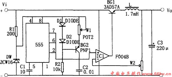
As shown in the figure, a step-up switching regulator power supply circuit composed of 555 is used. In the circuit, the transistor BG1 is used as a switching adjustment tube; the operational amplifier IC1 constitutes a comparison amplifier; and the 555 time base circuit is connected to an astable multivibrator. The oscillator generates a sawtooth voltage on C1 (Vmin=1/3Vz, Vmax=2/3Vz, the frequency is determined by W1 and C1) and is sent to the non-inverting input of comparator IC1. The sampled voltage is sent to the inverting input of the comparator. . The duty cycle of the IC1 output rectangular waveform is controlled by the sampling voltage. When the output voltage is a stable value, the sampling voltage is a value between 1/3Vz and 2/3Vz. When the output voltage rises (or falls) for some reason, the sampling voltage rises (or falls), causing the duty cycle of the IC1 output rectangular wave to decrease (or increase), and the on-time is shortened (or increased). The output voltage drops (or rises) to achieve a stable output voltage. Adjust W to control the output voltage.
Nantong Boxin Electronic Technology Co., Ltd. , https://www.ntbosen.com