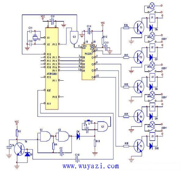
The circuit design of the common household appliance control module introduced here is to control the on/off of the power supply of different electrical appliances by telephone remote control. There are a total of 5 electrical appliances that can be controlled. The specific circuit design principles and circuit diagrams are shown below.
Circuit working principle: The purpose of the system is to control the on and off of the power supply of different electrical appliances by telephone remote control. There are a total of 5 electrical appliances that can be controlled. The signal for controlling the action of the controlled object is output from 5 channels of P1.3~P1.7. For example, if P1.3=1 can make T1 turn on, relay J1 pulls in; if P1.3=0, then J1 is released. . If P1.7=1, T5 can be turned on, relay J5 can be closed; if P1.7=0, then J5 is released. However, as can be seen from the figure, P1.3 is not directly connected to T1. P1.7 is not directly connected to T5, but is separated by an integrated block 74LS273. 74LS273 is an 8D latch, which means that the chip contains 8 D flip-flops, the input is D0~D7, and the output is Q0~ Q7. If the clear terminal CLR is low, the device is reset to zero, and the Q0~Q7 outputs are all zero. If the clear terminal is high, the input terminal will be changed whenever the trigger terminal CLK has a level. The state of D0~D7 will be latched into the device and output from Q0~Q7. As long as the CLK terminal is no longer triggered, this state will be remembered forever. It can be seen that the signal output from the AT89C2051 from P1.3-P1.7 is only sent out by memory first, and its control logic is the same as that directly received. The necessary condition for the input terminal to accept the input signal is that there is a positive transition at the end, which must satisfy two conditions at the same time: one is that the end of the decoder must be high, that is, the remote control transmitter has signaling; Second, must you send one? 0 changes to 1 hop signal. Only when the two conditions are satisfied at the same time, the AND gate outputs a positive transition signal to accept external information, which greatly improves the anti-interference ability of the circuit and prevents malfunction of the controlled object that may be caused by accidental interference.
Motor Wire
We supply variety of output lead wire for motor and motor wiring harness. With the properties of chemical erode resistance, excellent bendability in high and low temperature environment and impregnating varnish erode resistance even at 302°F (150°C), this kind of wire also can bear high temperature of 392°F (200°C) with FEP and silicone rubber insulations. All of our wires and cables are UL, RoHS and REACH complaint such as UL1430, UL3266, UL3122 and UL1332 etc.
Motor Wire,Single Phase Motor Wiring,Dc Motor Wiring,Motor Lead Wire
Feyvan Electronics Technology Co., Ltd. , https://www.fv-cable-assembly.com