Organic electroluminescence display, also known as organic light-emitting diode (OLED) or organic light-emitting display OrganicLightEmitTIngDisplay (OLED), has obvious advantages compared with the popular liquid crystal display (LCD) on the market, mainly as: autonomous illumination ( No backlight required, no viewing angle problem (angle of view up to 170°), light weight, thin thickness, high brightness, high luminous efficiency, fast response (1000 times of liquid crystal), high dynamic picture quality and wide temperature range (The temperature range is -40 ° C ~ 80 ° C), low power consumption, strong shock resistance, low manufacturing cost, flexible display. It is especially suitable for the instrument industry that requires high brightness and military products with higher requirements. Compared with LCDs that have matured in various fields, the development of OLEDs is still in its infancy, but with the gradual realization of these advantages, OLEDs will most likely replace LCD's position in the market. OLED is recognized by the industry as the most The next generation of displays for development prospects.
2 hardware structure designIn this paper, the single chip C8051F023 is used as the control core component of 128&TImes; 64 monochrome OLED. The screen is VGG12864G, which uses Solomon's SSD1303 as the dedicated driver IC. Realize text display and dynamic and static display of images. The overall hardware design block diagram is shown in Figure 1.
2.1 SSD1303 driver and interface circuit
The OLED display of the VGG12864G module has 128 columns and 64 rows. Figure 2 shows the block diagram of the SSD1303, showing the block diagram of the module logic and interface circuits. The user only needs to supply power to the interface, generate drive command signals and display data signals to illuminate the OLED screen. As can be seen from the figure, the output of the row and column drivers is connected to the OLED screen through FPC. The remaining MCU interface, voltage and current controllers need to be specially designed interfaces and driving circuits. The external signals of the module are only related to SSD1303. A relationship occurs. So understand the input characteristics and command system of the SSD1303, you can easily use this module. The SSD1303 is an IC driver from Monochrome that drives a monochrome OLED in a TAB package. This CMOS-based driver IC integrates row, column drivers, oscillators, contrast controllers, and graphics data memory (GDDRAM) to greatly reduce peripherals and power consumption. The maximum resolution that can be supported is 132 & TImes; 64, in which the 132×16 dot matrix area at the bottom of the OLED screen can display local colors of 4 colors, and can be programmed to achieve 64 levels of gray scale. When used for monochrome display, it can be programmed. Controls 256 levels of contrast. According to the microprocessor used (MPU), it provides 8-bit 6800 series MPU parallel, 8-bit 8080 series MPU parallel and SerialPeripheral Interface (SPI) serial three communication interface modes. The control command is input to the control command decoder through the MCU interface to perform command decoding, and then outputs clock, line synchronization, and field synchronization signals, thereby controlling the oscillation frequency of the OLED display, the voltage conversion module of the display device, and the row and column offset of the OLED display content. Driver module; if it is display data (128×64bits), the display data is input to the GDDRAM buffer through the MCU interface by the control circuit, then the data is decoded by the local color decoder, and finally the decoded display data is driven by the row and column driver. The OLED display shows a stable display effect on the OLED.
2.2 Power supply design
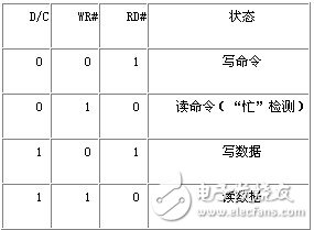
The hardware structure design block diagram is shown in Figure 2. The external hardware circuit DC-DC converter uses the TPS7333 chip to convert the 5V power supply into a 3.3V power supply, and the output power signal controls the voltage and current of the entire SSD1303 through the voltage and current controller. The whole system needs 3.3V and 12V power supply. The MCU (C8051F023 in this paper) needs to supply 3.3V power supply voltage. The OLED needs 3.3V logic power supply voltage and 9~12V drive power supply voltage. This drive power supply voltage is controlled by external power supply. The circuit is provided. 2.3 Various control signals are then controlled by the MCU. The MCU controls the SSD1303 driver IC through 13 interfaces of RES#, CS#, D/C, WR#, RD# and D0~D7 to control the OLED display. CS# is the chip select signal. When CS# is connected to low level, the MCU can communicate with the driver IC; RES# is the reset enable terminal. When connected to low level, all control registers are set to the factory default state. The image register is cleared; D/C is the data/command selection signal; WR# and RD# are the write and read select signals, respectively. When CS# is low, the read and write is valid on its falling edge. By changing the level of D/C, WR# and RD# interfaces, the MCU has four states for OLED control, which can be displayed in Table 1.
Table 1 read and write status list
2.4 read and write timing
As long as the VGG12864G's timing waveform is read and written, the OLED display can be completed. However, if you use software to program timing, you should consider many time parameters and have certain difficulties. In order to make data and commands easier to read and write, we use another method. As shown in Fig. 1, WR# and RD# are respectively connected to /WR and /RD of C8051F023, that is, P0.7 and P0.6. In the C language programming, the pointer type is defined as xdata type, which points to the off-chip memory. By assigning the pointer to the off-chip data storage area, when accessing the off-chip memory, /RD and /WR will be read and written. Automatically goes low, and the P3 port is the data bus. In the non-multiplexed mode, the upper 8 bits of the address bus use the P1 port, and the lower 8 bits use the P2 port. In the multiplexing mode, the upper 8 bits of the address bus still use the P1 port, which is low. The 8-bit and data bus are multiplexed with the P3 port, and the P2 port is not affected. Therefore, it is best to set the multiplexing mode (EMIOCF. 4=0). The P2 port can be used as another output port to freely control RES#, CS#, and DC. Although the address bus is not required, the address line is used when accessing off-chip memory, so it should be avoided. The timing waveform of the experimental results is shown in Figure 3. As long as CS# is low, writing or reading (reading) data or commands on the falling edge of WR# (RD#) can effectively perform the reading and writing.
3 software program designThe display program of the whole MCU control OLED is written in C language, and the main program flow chart is shown in Figure 4. Microcontroller initialization includes turning off the watchdog, clock initialization, port initialization, and initialization of timers and interrupts. OLED initialization includes on display, setting display mode, setting contrast controller, contrast setting (1~256), setting row and column start address, setting specific position color, setting serial port pin configuration. Clear OLED screen and OLED display are all written to GDDRAM, including read status, write command, write data subroutine, clear OLED screen will write "0", OLED display as long as the character code of the text or picture to be displayed Just fine. Read the status before each write (command or data) to see if the highest bit D7 is "0", also called "busy" detection. If it is "1", it means "busy"; otherwise, it is "free". It is only possible to write operations in the "free" state.
4 text and image displayThe VGG12864G has a built-in 128×64-bit display memory for storing display data, and Figure 5 shows the address structure of the RAM. The RAM capacity is 128×64=8192bits, which is divided into 8 pages (page0-page7), 8 lines per page, the first column of each page is just one byte, the low position is on, the high position is on; the pixels on the display are The display state is in one-to-one correspondence with each bit binary data of the display memory, and the data of the display memory is directly used as a driving signal for the graphic display. The data is displayed as "1", the corresponding pixel is displayed; the data is displayed as "0", and the corresponding pixel is not displayed. The character library of the displayed text or picture needs to be created by itself, but it is almost impossible to use it. You can use the font extraction software - "word extraction V2. 2". The software provides two modes of modal: horizontal and vertical. According to the RAM address structure of the OLED display data, the vertical mode is selected. Since the byte structure of the OLED module is high in the lower and lower bits, it is set to the byte reverse order, the font, font, size and display effect of the character. (Underline and strikethrough) can be adjusted as needed, and then adopt C51 format (A51 format can be adopted in assembly language programming) to generate a single character dot matrix display code, and finally display the effect on the OLED screen as needed. The code can be adjusted accordingly to get the desired character library.
The character library is generated according to the text or picture to be displayed, and the character code is written and stored in the GDDRAM module of the SSD1303 through the OLED display program, and can be stably displayed.
5 ConclusionA method based on single-chip microcomputer to realize OLED display is designed. For the function and characteristics, the circuit design of the relevant part is solved, and the display of text and static and dynamic pictures is realized on the developed system. The experiment proves that the design circuit is simple, and the system greatly reduces the cost, so that the system can be applied to small devices.
The etching plate heat exchanger sheet is specifically used in the plate heat exchanger to isolate the media and heat exchange plate, is an important part of the plate heat exchanger. The quality of the plate heat exchanger plate affects the overall performance and working condition of the plate heat exchanger. The main materials we use in plate heat exchanger sheet are stainless steel, titanium and titanium-palladium.
Half Etching Metal plates thin metal plates with corrugations, sealing grooves and angular holes, which are important heat transfer elements. Corrugation can not only strengthen the heat transfer and can increase the rigidity of the thin plate and thus improve the pressure-bearing capacity of the plate heat exchanger, and as a result of the liquid is turbulent, it can reduce the formation of sediment or dirt, play a certain "self-cleaning" role.
We custom plate heat exchanger sheet with drawings provided by customers. We are equipped with professional metal etching equipment and exposure development equipment. We can guarantee that our half etching plate heat exchanger sheet have straight surface line, and have no burr, high product accuracy.
Etching Plate Heat Exchanger Sheet,Custom Plate Heat Exchanger Sheet,Half Etching Metal Plates,Half Etching Plate Heat Exchanger Sheet
SHAOXING HUALI ELECTRONICS CO., LTD. , https://www.cnsxhuali.com