Inductive energy meters and ordinary electric energy meters have many defects, such as single function, poor anti-stealing effect, backward reading mode, easy damage to IC card, etc., in order to adapt to the trend of intelligent energy meter. The application of radio frequency identification (RFID) technology to the transmission of electricity information, better reflects the advantages of RFID contactless, passive, information security.
Radio frequency identification technology is a non-contact automatic identification technology, which uses white light signals to identify the target object and obtain relevant data.
The basic RFID system consists of two parts: an electronic standard (RF card), a reader and application support software and hardware. The RFTD tag consists of a chip and an antenna, and each tag has a unique electronic code. It is different depending on how the RF signal is transmitted. The tags are divided into active and passive two-port active tags that are powered by a built-in battery to actively transmit RF signals to the reader. After receiving the electromagnetic wave signal from the reader, the passive tag converts part of the electromagnetic energy into energy for working by itself to respond. The reader is responsible for transmitting the read signal to the tag and accepting the response of the tag. The object identification information of the tag is decoded, and the object identification information and other related information on the tag are transmitted to the host for processing. RFID applications support software and hardware to achieve valuable functions related to enterprise = or organizational applications.
Second, the working principleThe electric energy meter star chip sends the electric energy pulse signal and the current direction signal to the MCU for processing according to the voltage and current input signals. The MCU accumulates the power pulse. The electric quantity is calculated and stored, and the remaining electric blue is subtracted according to the current rate, and it is judged whether it is alarmed or powered off. The MCU constantly reads the clock and determines the rate at which it is currently running. The MCU also monitors the RS485 bus and infrared communication signals, receives or responds to commands, and performs serial communication. In addition, the meter also monitors relay status and battery voltage, power and other parameters, and reports and records non-nI: constant status.
The hardware circuit of a single-phase electronic energy meter based on RFID includes an energy metering unit, a radio frequency interface unit, a communication unit, a storage unit, a clock unit, a display unit, a keyboard processing unit, a load control unit, an MCU monitoring unit, and a DC Power unit and other parts. The block diagram of the smart energy meter is shown in Figure 1.
The microcontroller uses TI's ultra-low-power microcontroller MSP430F427, which has 16kB FLASH and 1kB RAM and comes with a 128-segment LCD driver. The metering section uses ADI's dedicated electrical energy metering sheet ADE7755. The RF read/write interface chip selects the MF RC500 chip for the reader of the PHILIPS company, and the low-cost passive Mafare MF1 card is used for the RF card. The storage part uses the E-PROM memory AT24LC16, and the real-time clock uses MAXIM's DS3231 with automatic temperature compensation. The lithium battery is used to ensure that the n1 of the electric energy meter is always running when the grid is powered off. The power-down monitoring unit uses the MAX705 to monitor the operation of the linear power network in real time. The load control part adopts BST-902-(50)A type magnetic holding relay of Shanghai Best Company to control the on and off of the load. The information exchange between the electric energy meter and the positioner adopts near-infrared photoelectric communication and remote HS485 bus mode. The energy meter uses buttons to enable key information inquiry.
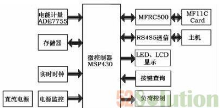
Figure 1 block diagram of the energy meter
Third, the hardware design3.1 Energy metering section
The ADE7755 uses a hybrid circuit design. The analog part includes two 16-bit Σ-Δ analog-to-digital converters (ADCs) and one reference circuit. The digital part is also called digital signal processing module, including phase corrector, high-pass filter, and multiplier. , low pass filter, digital frequency converter, etc. The hybrid circuit design combines the advantages of analog and digital circuits. The high-precision 16-bit Σ-ΔADC guarantees the linearity and accuracy of the signal. The phase correction, filtering, multiplication, and digital conversion in the digital domain are beneficial to improve the operation. The stability of the results. Therefore, the ADE7755 chip has high stability and accuracy even in long-term operation in extremely harsh environments, and its accuracy exceeds the requirements of the IEC61036 standard.
The metering circuit of the ADE7755 is shown in Figure 2. The voltage is connected to the voltage metering channel of the ADE7755 sample through the resistor divider network. The current is passed through the manganese copper sheet and sent to the current metering channel of the ADE7755. The linearity of the ADE7755 is 1‰, which ensures the accuracy of measurement. The CF frequency output is connected to the IO port of the MCU via an external filter circuit. The ADE7755 sets a minimum output frequency. When the output frequency generated by the load is lower than the specified minimum output frequency, F1, F2 and CF will not output any pulse. This frequency is 0.0014 of F1-4 corresponding to the full-scale output frequency. %. The pulse constant of the electric energy meter is 1600imp/kWh, the maximum load current is 40A, and the most suitable F1-4 frequency is 13.6Hz, that is, S0=1, S1=1, SCF=0.
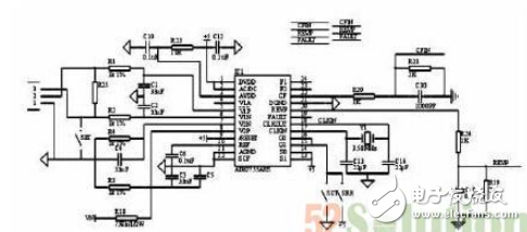
Figure 2 Energy metering circuit
3.2 RF Interface Section
The MF RC500 is a member of the highly integrated IC family for 13.56MHz contactless communication. The IC family utilizes advanced modulation and demodulation concepts and fully integrates all types of passive contactless communication methods and protocols at 13.56 MHz. The MF RC500 supports all layers of the IS014443A. The internal transmitter section can directly drive near-operating distance antennas (up to 100mm) without the addition of active circuitry, and the receiver section provides a robust and efficient demodulation and decoding circuit for ISO14443A compatible transponder signals. The digital part handles ISO14443A frame and error detection (parity and CRC). In addition, it supports the fast CRYPTOI encryption algorithm for verifying the Ml team RE series products. The convenient parallel interface can be directly connected to any 8-bit microprocessor, which provides great flexibility in the design of the reader terminal, making it ideal for applications in three-table.
RFID is a tool for pre-payment of electric energy meters. With RFID technology, we can easily realize pre-payment of electric energy meters. The MF RC500 chip is used as a reading and subtraction in RFID. Since the bus of the microcontroller does not expand, the MF RC500 cannot be operated directly as an external memory. In this regard, the author uses the analog bus to communicate with the MF RC500. Figure 3 shows a simplified diagram of the connection between the MF RC500 chip and the MSP43O. Here, the P6 port is connected to the DO-D7 of the MFRC500. Pl. 6 is connected to READ, Pl. 7 is connected to WRITE, Pl. 4 is connected to ALE, P2. is connected to RSTPD, and so on. The antenna part uses the antenna recommended in the data sheet.
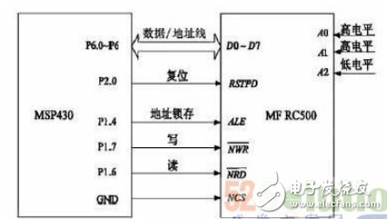
Figure 3 Connection diagram of MF RC500 chip and MSP430
Fourth, software design4.1 Main program flow
Software is the soul of electricity meters. The energy meter needs to complete the functions of energy metering, rate and time period control, query, display, electricity charge, load control, event recording, test output and so on. The power meter software design mainly adopts C language and adopts modular programming ideas, including the following modules: Power-on initialization module, main program module, power accumulation module, data storage module, interrupt program module, LCD display module, button processing module , rate processing module, real-time clock processing module, radio frequency read/write module, communication event processing module, load control module, etc. The main program flow chart is shown in Figure 4.
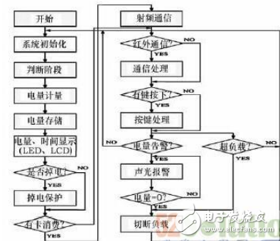
Figure 4 main program flow chart
The main program checks whether the accumulated power consumption of the pulse interrupt subroutine reaches a predetermined value (such as 0.1 kWh). When it arrives, this value is recorded in the unit of accumulated power consumption. Because it is a multi-rate electric energy meter, according to the real-time clock switching rate, it should be stored in the peak power, flat electricity or valley power unit according to the set time period, and display the power and related data according to the demand.
4.2 RF card reading and writing process
The time between the Mifare card and the reader antenna is ≤10 mm, the data transmission rate is 106 kbit / s, and the time for reading and writing can be less than 0.1 s. The card has an anti-collision feature. The entire circuit (except the coil) is integrated in one chip. The MCU first initializes the MFRC500. After the register is set, the MF RC500 can receive the MCU command execution operation and communicate with the Mifare card. The Mifare card can be operated according to the received instructions. However, the microcontroller does not read and write the IC card with a simple command, and requires a series of operations to complete the communication. Mainly include: 1) request wake-up; 2) anti-overlap (to prevent data errors caused by overlapping multiple cards); 3) select cards; 4) password authentication; 5) read and write operations. This series of operations of the Mifare card by the MCU must be performed in a fixed order. When a Mifare card enters the effective range of the RF antenna, the card reader will begin the series of operations described above. In order to improve the processing and response speed, the programming uses MCU assembly language and C language mixed programming. The interrupt service routine is written in assembly language. Other programs are written in C and call the basic library functions provided by PHILIPS to implement various functions.
Five, anti-interference designDue to the extremely harsh working environment of the meter, common sources of interference are: transients and high frequency pulses, low frequency pulses, lightning, radiated electromagnetic fields, harmonics and flicker. As a very important meter, the energy meter should ensure that the CPU does not run normally during the ten years of operation, the data is not lost, the chip is not reset abnormally, and even if an exception occurs occasionally, the system must be able to recover from the fault in time. Therefore, we must carry out detailed reliability design from both hardware and software.
5.1 Hardware anti-interference
1) Reduce the bandwidth and isolate the sensitive part of the system: If the power collection module collects the user's power from the power grid, it has a lot of interference, and it can be packaged separately with the power metering circuit and kept at a certain distance.
2) Using varistor: When the watt-hour meter is subjected to transient interference, the varistor responds extremely fast in nanosecond speed, forming a low-resistance shunt during over-voltage, which can strengthen the electric meter against the grid instantaneous surge. The ability to impact.
3) Photoelectric isolation: The pulse signal generated by the ADE7755 is optically isolated and then collected by the MCU to prevent the pulse interference signal from entering the MCU.
4) Anti-interference design of the circuit board: 1 The analog circuit is separated from the digital circuit; 2 The analog ground is separated from the digital ground and grounded at a single point; 3 PCB board is covered with a large area; 4 CPU chip pins are not suspended; 5 will have larger interference chips Place it at a position far from the microcontroller.
5.2 Software anti-interference
1) Repeat button detection: Repeat the detection with the timer to scan the button at 40Hz. Only when the button interface is detected for 3 consecutive times, it is considered that a button event occurs. This can obtain a reliable and effective signal after debounce, thereby avoiding button misoperation caused by interference.
2) Instruction redundancy: Instruction redundancy is to manually insert some single-byte instructions or rewrite valid single-byte instructions at critical points in the program. It is an effective measure to restore the program from the "flying" state. The prerequisite is that the PC pointer must point to the program run area and must be executed to the redundant instruction.
3) Software trap: When the random program enters the non-program area, through the setting of the software trap, the jump instruction is added, the random program is intercepted, and the program is quickly directed to a specified position, and then the error processing is performed to make the program re Be put on the right track.
4) Program watchdog timer (watchdog): The watchdog monitors the running status of the program to determine whether the program enters an endless loop or a program "running" phenomenon, thereby forcing the program to return to the reset state. The main program of the system is a loop structure, and the watchdog clear instruction is set on the loop path.
Sixth, the conclusionThe development trend of electric energy meters is high precision, versatility and intelligence. Radio frequency identification technology has become a new force in information technology. The innovation of this program is reflected in:
1) Applying TI's 16-bit MSP430 microcontroller to the energy meter design, its ultra-low power performance promotes the development of “low carbon economyâ€;
2) RF card replaces contact IC card, which has long life, easy to use and safe data transmission;
3) Multi-function. The meter can realize multi-rate, time-based billing, pre-paid, load control, near-infrared meter reading and remote RS485 bus meter reading, power-down protection and other functions.
Power Accessories,Steel Wire Tension Clamp,Rubber Insulation Tape,Rubber Arrester
YIXING FUTAO METAL STRUCTURAL UNIT CO.,LTD( YIXING HONGSHENGYUAN ELECTRIC POWER FACILITIES CO.,LTD.) , https://www.chinasteelpole.com