The stepping motor is an open-loop control element that converts an electrical pulse signal into an angular displacement or a linear displacement. In the case of non-overloading, the rotational speed and stop position of the motor depend only on the frequency of the pulse signal and the number of pulses, and are not affected by the load. The effect of the change is to add a pulse signal to the motor and the motor to turn a step angle. The existence of this linear relationship, coupled with the stepper motor only periodic error without cumulative error. It is very simple to control the change with a stepping motor in the control field such as speed and position.
The small series of this paper mainly introduces the structure and working principle of reactive stepping motor. The three-phase and four-phase reactive stepping motor are taken as examples to explain its working principle.
The reactive stepping motor is a conventional stepping motor that is rotated by a magnetic rotor core that interacts with a pulsed electromagnetic field generated by the stator.
The working principle of the reactive stepping motor is relatively simple. There are many small teeth evenly distributed on the rotor. The stator teeth have three excitation windings, and their geometric axes are respectively shifted from the rotor tooth axis. The position and speed of the motor are in a one-to-one correspondence between the number of times of conduction (number of pulses) and the frequency. The direction is determined by the order of conduction. In the market, there are generally two, three, four, five-phase reactive stepping machines.
Reactive stepper motor structureThe reactive stepping motor has many structural forms, and is divided into a single-stage type and a multi-stage type according to the number of segments of the fixed rotor core.
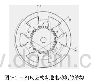
1, single-stage stepper motor
The single-stage stepping motor is a section of iron core. Since the phase windings are evenly arranged in the circumferential direction, they are also referred to as radial split phases. It is one of the most used forms of stepper motors. Figure 4-4 shows the radial cross-section of a phase-reaction stepper motor. The stator core is made of silicon steel sheets, the stator magnet is extremely salient, and the poles of the poles are small. There are three sets of control windings on the stator, and each set has two series-connected central control windings wound on two diametrically opposed poles. Each set of windings is called a phase, and the three-phase windings are connected in a star shape. Therefore, the number of stator poles is usually twice the number of phases, that is, 2p=2m (p is the pole logarithm, m is the number of phases). There is no winding on the rotor, and there are also For even teeth, the pitch of the teeth and the pitch of the small teeth on the stator pole must be equal, and the number of teeth of the rotor is limited. The advantage of this type of construction is that it is easy to manufacture, the accuracy is easy to ensure, and the step angle can be made smaller. Easy to get a higher start and run frequency. The disadvantage is that when the diameter of the motor is small and the number of phases is large, it is difficult to phase-separate in the radial direction, and the power consumption is large, and there is no positioning torque when the power is off.
2, multi-stage stepper motor
The multi-stage stepping motor is divided into m segments by the number of phases along the axial direction of the motor. Since the phase windings are distributed along the axial direction, they are also referred to as axial split phases. There are two kinds of structural features according to the magnetic circuit. One is that the main magnetic circuit is still radial, and the other is that the main magnetic circuit includes an axial portion.
Reactive stepper motor features1. Higher torque moment of inertia ratio
2, higher step frequency, fast frequency response
3. It can be freely rotated when it is not energized, with simple structure and long life.
Working principle of reactive stepping motor1. Working principle of three-phase reactive stepping motor
Rotation:
If the phase A is energized and the B and C phases are not energized, the teeth 1 are aligned with A due to the action of the magnetic field (the rotor is not subject to any force and below). If phase B is energized, when phase A and phase C are not energized, tooth 2 should be aligned with B. At this time, the rotor is shifted to the right by 1/3ã¦, at which time the teeth 3 and C are offset by 1/3ã¦, and teeth 4 and A are Offset (ã¦-1/3ã¦)=2/3ã¦. If the C phase is energized, the A and B phases are not energized, and the tooth 3 should be aligned with C. At this time, the rotor is shifted to the right by 1/3 ã¦, and the tooth 4 is aligned with the A offset by 1/3 æ¤æ—¶. If the A phase is energized, the B and C phases are not energized, the teeth 4 are aligned with A, and the rotor is shifted to the right by 1/3 㦠so that the A, B, C, and A are respectively energized, and the teeth 4 (ie, the teeth of the tooth 1) Move to phase A, the motor rotor turns to the right by a pitch. If the A, B, C, A... is continuously energized, the motor rotates 1/3 turn per step (per pulse) and rotates to the right. If A, C, B, A... is energized, the motor will reverse.
It can be seen that the position and speed of the motor are in a one-to-one correspondence between the number of times of conduction (number of pulses) and the frequency. The direction is determined by the order of conduction. However, due to the consideration of torque, stability, noise and angle reduction. The conductive state of A-AB-B-BC-C-CA-A is often used, so that 1/3 æ¯ of each step is changed to 1/6 ã¦. Even through the different combinations of two-phase currents, the 1/3 turns into 1/12 ã¦, 1/24 ã¦, which is the basic theoretical basis for the motor subdivision drive.
It is not difficult to introduce: there is m-phase excitation winding on the stator of the motor, and its axis is offset from the rotor tooth axis by 1/m, 2/m...(m-1)/m,1 respectively. And the conduction of the motor in a certain phase sequence can be controlled by forward and reverse - this is the physical condition of rotation. As long as this condition is met, we can theoretically manufacture stepper motors of any phase. For cost and other considerations, the market generally has two, three, four, and five phases.
Torque: Once the motor is energized, a magnetic field (magnetic flux Ф) will be generated between the stator and rotor. When the rotor and the stator are offset by a certain angle, the force F is proportional to (dФ/dθ). The magnetic flux Ф=Br*S Br is magnetically dense, S is The magnetic permeability area F is proportional to L*D*Br, which is the effective length of the iron core, and D is the rotor diameter Br=N·I/RN·I is the number of excitation winding amps (current multiplied by the number of turns) R is the magnetic resistance. Torque = force * radius torque and motor effective volume * amperage * magnetic density is proportional (only consider linear state) Therefore, the larger the effective volume of the motor, the larger the number of excitation amps, the smaller the air gap between the stator and rotor, the motor torque The bigger, and vice versa.
2, four-phase reactive stepper motor working principle
The stepping motor is a four-phase stepping motor and is powered by a unipolar DC power supply. As long as the phase windings of the stepper motor are energized at the appropriate timing, the stepper motor can be stepped. FIG. 1 is a schematic diagram of the working principle of the four-phase reaction type stepping motor.
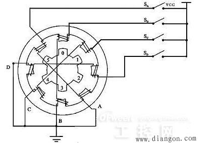
At the beginning, the switch SB is turned on, SA, SC, and SD are disconnected, and the B-phase magnetic poles are aligned with the rotor No. 0 and No. 3 teeth. At the same time, the No. 1 and No. 4 teeth of the rotor and the magnetic poles of the C and D phase windings are misaligned. 2, the 5th tooth and the D, A phase winding magnetic poles produce wrong teeth. When the switch SC is turned on and the SB, SA, and SD are turned off, the rotor rotates due to the action of the magnetic lines of the C-phase winding and the magnetic lines between the No. 1 and No. 4 teeth, and the magnetic poles of the No. 1, No. 4 and C-phase windings are aligned. . The 0th and 3rd teeth and the A and B phase windings produce the wrong teeth, and the 2nd and 5th teeth and the A and D phase winding magnetic poles produce the wrong teeth. By analogy, the four-phase windings of A, B, C, and D are alternately powered, and the rotor will rotate in the A, B, C, and D directions.
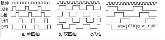
The four-phase stepping motor can be divided into three working modes: single four-shot, double four-shot, and eight-shot according to the order of power-on. The step angle of the single four-shot and the double-four beat is equal, but the turning moment of the single four-shot is small. The step angle of the eight-shot working mode is half of the single-four-shot and double-four-shot. Therefore, the eight-shot working mode can maintain a high rotational torque and improve the control accuracy.
The power-on timing and waveform of the single four-shot, double four-shot and eight-shot modes are shown in Figure 2.a, b, and c, respectively:
"What is a hybrid stepper motor _ the difference between hybrid stepper motor and reactive stepper motor"
"Detailed structure and working principle of HB type hybrid stepping motor"
"After reading the relationship between HB hybrid stepping motor and the number of phases, the number of rotor teeth and the number of main poles"
According to the type of sensor, the Touch Screen is roughly divided into infrared type, resistance type, surface acoustic wave type and capacitive touch screen four kinds. The design of capacitive touch screen is reasonable, but the problem of image distortion is difficult to be solved.
Capacitive touch screen
The touch screen works by using the body's current induction process. A special transparent metal conductive substance is coated on the surface of the glass. When a conductive object touches the glass, it changes the capacitance of the contact, so as to detect the position of the touch. But touching a non-conductive object with a gloved hand or hand does not respond because of the addition of a more insulating medium.
Capacitive touch screen can sense light and fast touch, anti-scratch, not afraid of dust, water and dirt influence, suitable for harsh environment. However, capacitance varies with temperature, humidity or environmental electric field, so its stability is poor, low resolution and easy to drift.
Capacitive Screen,Projected Capacitive,Capacitive Touch Panel,Projected Capacitive Touch
TONYA DISPLAY LIMITED , https://www.tydisplay.com