This paper introduces the analysis of the common-emitter, common-collector, and common-base amplifier circuits under the DC path.
Common-shot amplifier circuit
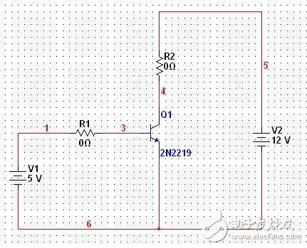
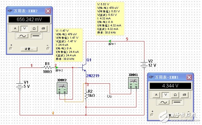
The basic common-emitter amplifier circuit is shown in the figure, and should be often encountered in the analog circuit book, but at that time it is more to analyze the static working point, AC and DC amplification, but in the real circuit design, R1 and R2 What is the range of values? Or how should they take values?
It is known that the NPN type tube 2N2219 is a silicon type tube, and the saturation voltage Ube=0.7V when it is in normal operation. The first is the choice of R1. The maximum Ib of 2N2219 is 800mA. It is obviously not possible to select R1 to make its current value less than 800mA. Generally, the current value of Ib is several mA to uA, because the maximum value of Ic is 800mA, according to ordinary 100 times the magnification Ib can only reach 8mA
According to this standard, you can take the value, for example, R1=10k (first analysis and analysis is appropriate), then Ib=0.43mA, assuming that the magnification is 100 times (rough estimate, so take this value) then Ic=43mA, in order to To make the triode work in the amplification area, Uce "Ube" must be required, then Uce should be at least 0.7V, um, assuming 1v (should be larger than this, because there will be an AC signal under dynamic conditions to prevent saturation distortion) Then, R2 should take the value of R2=(12-1)V/43mA=256Ω, that is, R2 cannot be larger than 256 (estimation, magnification, etc., but it is near this). So you can take R2=200Ω and below (the smaller the R2, the larger the Uce)
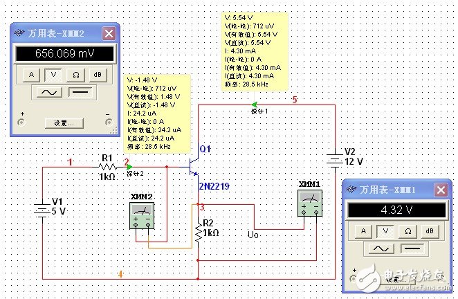
The simulation is as follows
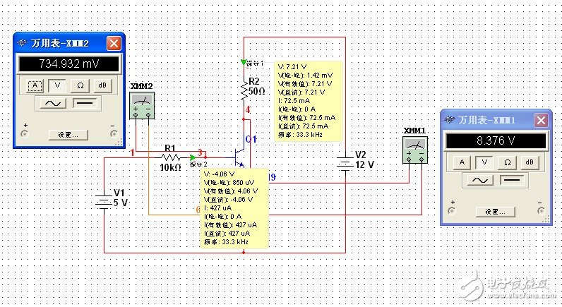
Figure 2 R2=50Ω

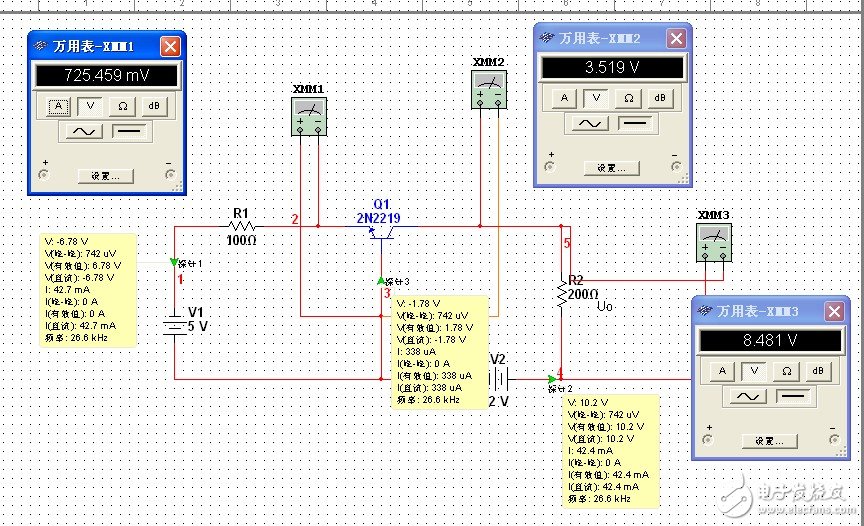
Figure 3 R2 = 200Ω
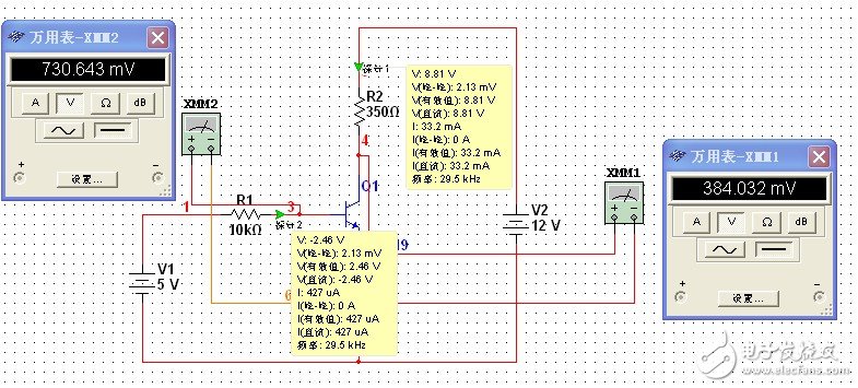
Figure 4 R2 = 350Ω, entering the saturation region.
If R1=1k can be calculated again, Ib=4.3mA, Ic=430mA, R2 can only take 26Ω or less, so the resistance requirement is too high.
At the same time, we should notice a phenomenon. When R2=50Ω or 200Ω, Ic changes when Ib does not change, from 77.5mA to 45.5mA. It does not seem to coincide with the triode output characteristic curve (like the nature of the saturation region). Almost: Ic increases with the increase of Uce).
Let's talk about the various states of the triode:
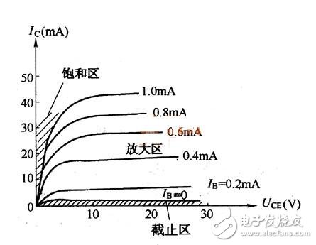
Figure 5 Transistor output characteristic curve
In fact, the graph is only the curve in the ideal state. In practice, the parallel part should also be upward, but the angle is not as large as in the saturated region. In judging whether a triode is in the saturation region, it can not be seen whether Ic increases with the increase of Uce, but it should be seen that when Ube increases, Ib increases, but Ic does not increase much.
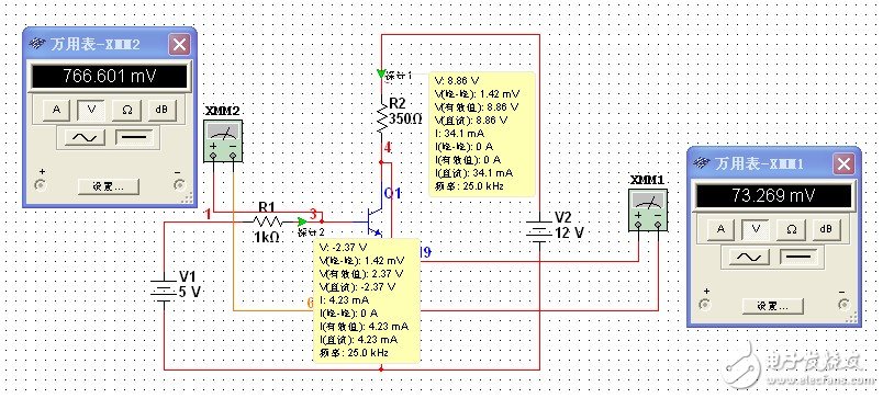
Figure 6 Note that compared with Figure 4, Ib is significantly increased but Ic is basically unchanged.
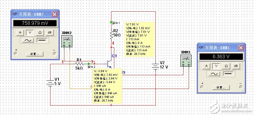
Figure 7 Compared with Figure 2, Ic also increases as Ib increases, in the magnified area.
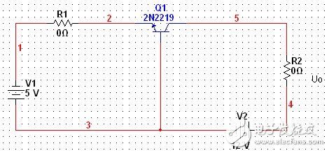
Common collector amplifier circuit
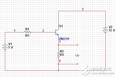
Figure 8 common collector amplifier circuit
How to choose R1 and R2 in Figure 8? Since R2 is on the emitter, the Uce voltage must be greater than 5v, that is, the collector junction is reverse biased. In this case, it is sufficient to ensure that the emitter junction is positively biased and the Ib current value is appropriate. Therefore, the choice of R1, R2 can only be followed by a dozen requirements, more extensive, can be from a few hundred ohms to a few k
The choice of R1 has little effect on the circuit current. The key is that the larger the R2 and R2, the smaller the base and emitter currents.
Common base amplifier circuit:
How much should R1 and R2 be selected?
Ie is generally in the tens of mA, assuming Ie = 43mA, at this time R1 is about 100Ω, Ic is equal to Ie = 43mA, in order to ensure Uce reverse bias, but also to ensure that Uce "1v" R2 maximum 256Ω, according to Uo The output can take R2 between tens and 200
Stainless Steel Thick Plate,Stainless Steel Escutcheon Plate,Cold-Rolled Stainless Steel Sheets,Stainless Steel Thick Plate 304
ShenZhen Haofa Metal Precision Parts Technology Co., Ltd. , https://www.haofametal.com