The main failure mechanisms of magnetic bead magnet rings are mechanical stress and thermal stress. As a magnetic conductive material, the magnetic bead magnetic ring is highly brittle, and the magnetic bead body is prone to cracking when subjected to external mechanical stress (such as impact, collision, PCB warpage). Therefore, the use of magnetic beads and magnetic rings requires attention to the following:
1. When the magnetic beads are laid out on the PCB, they must not be within the 3cm range of the straight plug connector. The flat plug connector is not subject to this limitation;
2. After the magnetic ring is installed on the wire, it needs to be fixed, the fixing material is made of silica gel, and the bonding method is fixed after hot melting;
3. One of the failure mechanisms of the magnetic beads is thermal failure. The reason for the failure is that a large current flows through the magnetic beads, and the current generates heat loss (Q=I2*Rdc) on the DC resistance Rdc of the magnetic beads, and the heat is large. Can not be dissipated in time, will cause the magnetic beads to be unevenly heated as a whole, resulting in internal stress leading to cracks, the occurrence of cracks, the magnetic permeability of the magnetically permeable material is damaged, so the magnetic field lines of the high-frequency wave signal on the magnetically permeable material The transmission is affected, making the filtering effect worse.
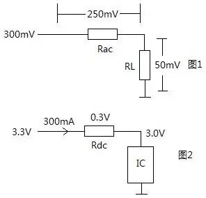
Example: The rated voltage of the power supply is 3.3V and the rated current is 300mA. The remote IC on the board requires the power supply voltage to be at least 3.0V, and the noise of 100MHV and 300mVpp is required to reach 50mVpp after magnetic bead filtering. How should the magnetic beads be selected?
solution:
1. For a 100MHz signal, the 300mV noise needs to be filtered and attenuated to 50mV, which means that the voltage division on the magnetic beads should reach 250mV, assuming load RL=50Ω, as shown in Figure 1. Then Rac / RL = 250 / 50, where RL = 50 Ω, get Rac = 250 Ω (at 100 MHz)
2, the rated current of the power supply is 300mA, and the derating factor is 0.75, then select the magnetic bead with the minimum rated current not less than 300mA/0.75=400mA;
3. The IC requires that the minimum supply voltage should not be lower than 3.0V. The maximum voltage drop on the DC resistance Rdc of the magnetic bead must be no more than 0.3V. For example, (Fig. 2), that is, 300mA*Rdc<0.3V, Rdc<1Ω is obtained.
4. In summary, it is concluded that the magnetic bead index meets the following requirements to meet the requirements of the problem: Rac ≥ 250 Ω (at 100 MHz), rated current not less than 400 mA, Rdc < 1 Ω.
D-sub Connector Contacts
A D-sub connector is a form of connector commonly found in electronic and computer systems. It consists of a D shaped metal band and two or more parallel rows of either pin contacts (male) or socket contacts (female). D-sub connector contacts can vary in size, material, current rating, length and resistance.
The most common type of connector is the crimp contact. These are assembled by inserting a stripped wire end into the cavity at the rear of the contact. The cavity is then crushed using a crimp tool, gripping the contact to the wire.
What are D-sub connector contacts used for?
The D-sub connector contacts carry the signal from the source to the destination across the D–sub connection.
Types of D-sub connector contacts
Most D-sub connectors are supplied with contacts ready in place. Contacts can be replaced if damaged or if the application of the D-sub connector is to be changed from the original design specification.
High-current, high-voltage, or co-axial inserts require larger contacts. The material of the D-sub connector contact can be changed if the robustness or quality of the connection needs to be improved.
D-SUB coaxial contact,D-Sub Connectors Contacts,D-Sub Plug Connectors Contact,D-Sub Receptacle Connectors Contact
ShenZhen Antenk Electronics Co,Ltd , https://www.antenkcon.com