0 Preface
This article refers to the address: http://
The ISD series voice circuit is a new patented product of the US ISD (InformationStorage Device) company, which breaks the traditional first A/D and then D/A mode, and uses the unique direct storage analog signal technology to greatly increase the storage density. And the analog signal can be saved permanently. The ISD series circuit has established its indisputable position in the field of voice applications due to its natural sound quality, convenient use, single-chip storage, repeated recording and playback, low power consumption, and power-off. Currently, it has been in communication equipment and intelligence. Instruments, security alarms, voice report stations, report quotes, voice explanations, voice recording, voice repeat, teaching instruments, smart toys, electronic gifts and other fields have been widely used.
In this paper, a microcomputer speech board is designed with single chip microcomputer 89C2051 and ISD2560, which realizes segmental recording and combined playback of voice. You can also modify the software to achieve the entire paragraph of admission and loop playback. This product can be used as a subsystem of a voice service system without the need to use a dedicated ISD voice development device.
1 ISD2560 voice recording and playback circuit composition
The ISD2500 series of voice chips can be easily interfaced to the CPU via the SPI protocol. This article uses the ISD2560 chip to form a single-chip universal development board using the most commonly used MCS-51 language single-chip 89C51, to combine with the ISD2500 series of voice chips, allowing users to develop a variety of new intelligent digital voice products.
The assembled devices on the development board include:
◇AT89C2051 single-chip microcomputer, the device contains 8031 ​​core, 4 KB program memory that can be repeatedly erased, and 32 I/O ports, and operates with 5 V voltage;
â—‡ISD2560 voice chip, using analog memory technology with excellent sound quality, can be recorded and replayed for 60 seconds;
â—‡LM386 power amplifier with 0.5 W drive capability;
AT24C01 (optional) I2C bus serial memory;
In addition, there are components such as an electret microphone (MIC), a microphone amplifier, a volume potentiometer, and an LED tube. When the board is working, the external power supply voltage of the board is 12 V (regulated), the external speaker is 4 ~ 16 Ω / 0.5 W, the working current is 25 ~ 30 mA during recording, and 50 ~ 80 mA during playback. The quiescent current is 13 mA, and the accompanying software is provided with the demo program function.
2 ISD2560 and microcontroller interface circuit
A0~A9 of ISD2560 are address lines, which have a total of 1024 combined states. The first 600 states are normally used for addressing internal memory, and the last 256 states are used for operating mode. The system is designed to operate directly on the address.
In the interface between the system and the microprocessor, the P/R recording and playback control terminal is in the playback state when the high level is at the high level, and the recording state is at the low level; the P3.5 and P3.7 terminals are used for recording and playback. Stop control, usually used with P/R end; P3.4 end is the end of each piece of information signal output, the signal is a negative direction signal, the time is 12.5ms, and its rising edge flag information ends.
The MIC in the system is the microphone preamplifier input; MIC REF is the microphone compensation end, AGC is the automatic gain control terminal; ANA IN and ANA OUT are the analog signal input and output terminals, and the coupling capacitance between them is usually taken. It is 0.22 to 1 μF.
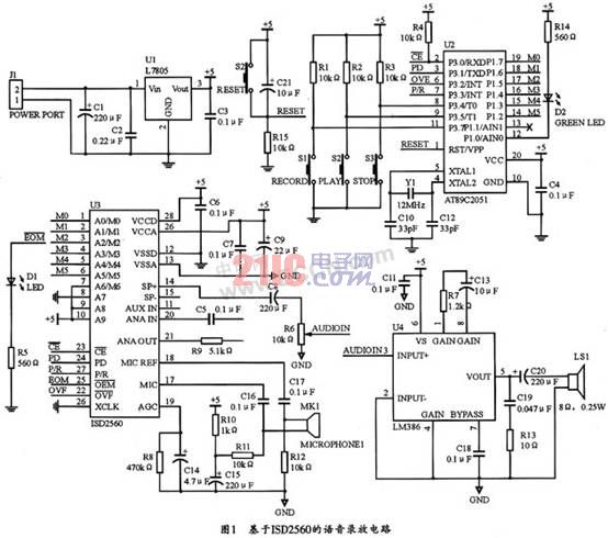
The voice recording and playback circuit based on ISD2560 in this system is shown as in Fig. 1. Under normal circumstances, the P1 port, P3.4 and P3.5 of the MCU can be connected to the address line of the ISD2560 to set the starting address of the voice segment. P3.0~P3.3 are used to control the recording and playback status. P3.7 is an extended recording button that can be used for recording.
3 system working principle and program design
Although the ISD2560 provides an address input line, the address of its internal information segment cannot be read. Therefore, an operation mode that does not require an address is usually used. However, to read the internal information address of the ISD2560, a dedicated ISD development device is required, and these devices are relatively expensive. To this end, the system uses a microcontroller to control. The method does not need to read the information address, but directly sets the start address of the information segment. There are many ways to implement this idea. The first method is because the address resolution of the ISD2560 is 100ms. Therefore, the internal timer of the MCU can be used for 100 ms, and then the counter is used to count the number of times of the MCU. Thus, the counter value is the address unit occupied by the speech segment. . This method can make full use of the EEPROM inside the ISD2560, so the method can be utilized when there are many fields; if the voice field is small, the second way can be used: that is, the address unit is directly allocated according to the content of each field. Generally, it is calculated by 3 words per 1 s, 180 words can be said for 60 s, and then the address unit required for the speech segment is calculated according to the address resolution of the ISD2560 of 100 ms. This system uses this method.
3.1 AT89C2051 recording and playback control of ISD2560
When recording, first press the record button, the MCU sets the start address of the voice segment through the mouth line, and then makes the PD terminal, P/R terminal and other related ports low to start recording; when the recording ends, the MCU makes these The port returns to high level to complete a voice recording. Then in the same way, you can also take the second paragraph, the third paragraph, and so on. It is worth noting that the recording time generally cannot exceed the preset time of each speech.
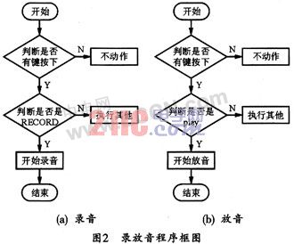
During playback, the corresponding voice segment start address can be found according to the voice content to be played, and sent through the interface line. Then set the P/R terminal to the high level, the PD terminal to the low level, and let it generate a negative pulse to start the playback. At this time, the MCU only needs to wait for the information end signal of the ISD2560 (ie, the EOM is generated). Since the signal is a negative pulse and the rising edge of the negative pulse, the segment of speech is played, so the MCU must detect the rising edge to play the second segment. Otherwise, the played speech will be discontinuous, and There will be buzzing, which must be taken into account when programming the software. Figure 2 shows the block diagram of its recording and playback.
The specific operation method is as follows:
(1) Recording
Insert the jumper on the “REC†side, which is the recording state. Press the “REC†button, the indicator light will be on, and the microphone can be recorded on the board. When the button is released, the recording stops and forms a segment. Press again to record a paragraph. During operation, press the “STOP†button to reset, and when recording again, it will start from the first segment.
(2) playback
Insert the jumper on the “PLAY†side for the playback state. After that, press the “PLAY†button to play a segment. After a period, the playback will stop automatically, and then press “AN†to play the next segment. During the operation, press the “STOP†button to reset, and then play again, starting from the first segment.
3.2 Programming
This program is written with AT89C2051 as the controller of ISD2560 and the crystal frequency is 12 MHz.
The recording program for taking voice messages and the source program for playing the voice are given below. In fact, playback can also be combined according to the actual situation during playback. The program can also be expanded as needed. Its ISD2560 voice recording and playback system program is as follows:


Thereafter, during recording, the first press of the record button starts recording, and the second press of the record button indicates pause (ie save, set EOM). After pausing the recording, press the playback button to start playback from the address pointer at 0. When recording, the recording can be stopped by the high pulse at the PD (pin P3.1).
When playing, the first press of the play button will start playback. During playback, press the play button again to pause, and press the play button a third time to resume playback at the pause. If you press the record button after the second play button is pressed, you can start recording from the pause. During playback, the high pulse generated by the PD (Pin P3.1) can be used to stop playback and the address pointer is reset to 0. If there is no PD high pulse during playback, it will continue to play until the chip overflow occurs, and then return the address pointer to 0, and start looping.
Here is the recording subroutine:

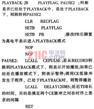
The system's playback subroutine is as follows:
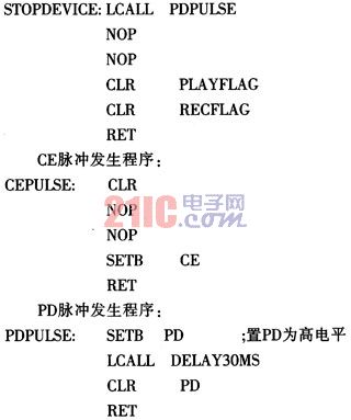
Stop recording or playing the subroutine as follows:
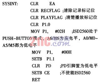
System initialization program:
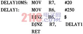
10ms delay program:
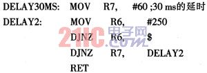
30ms delay program:
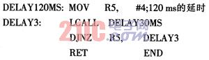
120 ms delay program:
4 Conclusion
The voice recording and playback circuit has the advantages of simple structure, low cost, convenient adjustment and high reliability. Proof of actual use. The system can meet the requirements of normal voice recording and playback. Moreover, it can also be used for other voice recording and playback situations by appropriate adjustment.
REMOTE CONTROL SOCKET
Important Safeguards
When using any electrical appliance, in order to reduce the risk of fire, electric shock and/or injury to persons, basic safety precautions should always be follow8d. including:
• The appliance is for household and indoor use only.
• Before plugging in. check that the voitage on the rating label is the same as the mains supply.
• To protect against electric shock, do not immerse any part of the product in water or other liquid.
• This socket is intended for use by competent adults only and children should be supervised at all times.
• Do not use the socket for other than its intended use.
• This socket can be used by children aged from 8 years arxl above and persons with reduced physical, sensory or mental capabilities or lack of experience and knowledge if they have been given supervision or instruction concerning use of the appliance in a safe way and understand the hazards involved. Children shall not p<ay with the appliance Cleaning and user maintenance shall M be made by children without supervision.
• Children of less than 3 years should be kept away unless continuously supervised.
Children from 3 years and less than 8 years shall only switch on/off the appliance provided that it has been placed or installed in its intended normal operating position and they have been supervision or instruction concerning use of the appliance in a safe way and understand the hazards involved. Children aged from 3 years and less than 8 years shall not plug in. regulate and clean the appliance or perform user maintenance.
• Don't use this socket in the immediate surroundings of a bath, a shower or a swimming pool.
• In case of malfunction, do not try to repair the socket yourself, it may result in a fire hazard or electric shock
Do Not Exceed Maximum a680W
Place the LR44 batteries provided into the compartment in the back of the Remote Control, please insert as sho*/m in the back of the compartment to ensure the polarity is correct.
Programming Instructions
• Plug the Remoce Socket$($)lnto the wall socket(s) and switch on the mams supply, the red LED will flash every second.
• If the LED is not flashing press & hold the manual ON/OFF button for 5 seconds until it Hashes
•Press any ON switch on the Remote Control for approximately 2 seconds and the Remote Socket(s) learn the code. The LED will stop flashing top confirm the codehas been accepted.
• Any number of Remote Sockets can be programmed to one Remote Control ON button to create multiple switching.
• To programme o<her Remote Sockets on different Remote Control ON buttons repeat the prevous steps
• If the mains supply is turned off the Remote Sockets v/ill lose their code and it wil be necessary to re-pcogramme.
Operation:
• Plug your appliance(s) into the Remote Socket(s)
• Press the programmed ON or OFF button on the Remote Control to control the Remote Socket.
♦ The Remote Sockets can also be operated manually using its ON/OFF Button Trouble shooting
If a Remote Socket does not react to the Remote Control please check the followng:
♦ Low battery in tbo Remote Control
• Distance too large between the remote control and the recerver (ensure the range distance is no more than 20 clear Metres) and free from obstacle that may reduce the distance.
• If programming has not been successful, tum the power off and back on then follow the programming steps above.
How to decode
• Press the manual ONX)FF button for 5 seconds until the red LED flashes once per
second to confirm de-coding is successful
♦ Press the ALL OFF switch on the Remote Control for more than 3 seconds, the LED
flashes once per second to confirm (decoding successful.
Voltage: 240V-/50HZ
Max power rating: 3680W max.
Remote frequency:
Remote range:
Battery Type:
433.92MHz
230 Metres
Button Cell 2x1.5V LR44 =
Please check with your local waste management service authority regarding regulations for the safe disposal of the batteries. The batteries should never be placed G municipal waste.
Use a battery d^posal facility if available
M
For eioctncal products sold within the European Community. At the end of the electrical products useful life, it should not be disposed of wth household waste. Please recycle faaMies exist. Check with your Local Authonty or retailer for recycling advice.
C€
Remote Control Electrical Outlets,Remote Control Outlet,Remote Controlled Power Socket,Wireless Remote Control Outlet,Mini Wireless Remote Control Outlet,Wireless Remote Power Switch
NINGBO COWELL ELECTRONICS & TECHNOLOGY CO., LTD , https://www.cowellsockets.com