The RF front-end low noise amplifier (LNA) circuit is an important part of the front-end circuit design of radio equipment. Since the actual radio propagation environment is usually harsh, the LNA must be considered in its RF front-end circuitry. As a key circuit in the RF module, the LNA directly affects the performance of the receiver. On the other hand, the design of the LNA is also one of the most challenging aspects of radio-related circuit design. This is mainly due to the fact that it also needs to meet high gain, low noise, good input and output matching and unconditional stability at the lowest possible operating current.
As one of the mobile communication standards, CDMA2000 is an important technical standard for the third generation mobile communication system and has received extensive attention worldwide. In fact, the design of the LNA circuit is one of the main contents of the base station circuit design under this standard. At the same time, due to the special application of mobile communication equipment and CDMA2000 multiple access mode, suppressing interference/noise, improving gain and maintaining its stability are the basic starting points of related circuit design. Therefore, combined with the design problem of CDMA2000 base station LNA circuit, it can discuss some key problems and solutions of RF LNA circuit design under general circumstances. This also provides a practical background for the discussion of general issues.
2. Several problems in the design of RF LNA circuitThe design of the low-noise amplifier circuit should first focus on both low noise and high gain. In the case of high gain, the stability of the circuit must be taken into consideration from the reliability of its performance. In order to realize the comprehensive consideration and compromise of these factors in the actual circuit design, the related issues are discussed one by one.
2.1 Noise problems and how to deal with themThe main sources of noise that cause the noise characteristics of the amplifier circuit to deteriorate include flicker noise, thermal noise, and shot noise. Among them, the flicker noise is also called 1/f noise, and its value is related to the semiconductor material. The power spectral density is inversely proportional to the frequency. Therefore, in the case of radio frequency, it may not be considered too much. Thermal noise is the noise introduced by the thermal motion of electrons, which is mainly controlled by the ambient temperature and is independent of current. In the case of radio frequency, this noise is affected by the increase of the frequency of the external field, and its magnitude will increase significantly with the increase of the frequency. Shotgun noise is not directly affected by temperature. The amount of shot noise is proportional to the operating current. In summary, as the suppression of noise in the RF low-noise amplifier circuit, the suppression of thermal noise and shot-shot noise should be considered.
In general, noise problems can be effectively solved by selecting low-noise devices, reducing circuit insertion loss, improving linearity, and reducing circuit power consumption [1]. Note that the above methods, including the selection of low noise devices, are mostly related to the specific design of the circuit. Therefore, in the actual design, the above processing methods should be flexibly applied according to the requirements of relevant indicators.
2.2 Gain problem and its treatmentIn order to achieve high gain of the circuit (generally in the tens of dB), it is usually necessary to employ a multi-stage amplifying circuit, such as the two-stage amplifying circuit shown in FIG. This treatment method has been widely used in practice.
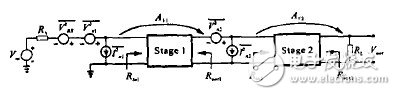
Figure 1 two-stage amplification circuit model
In order to take into account the consideration of noise, the noise and gain of the multi-stage amplifier circuit should be considered together. For class m amplifiers, the total noise figure is determined by the noise figure NF and gain Av of each single-stage circuit [2], ie
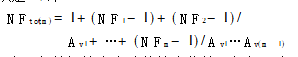
Since the amplification factor of each single-stage amplifying circuit is generally much larger than 1, it is obvious that the total noise figure of the multi-stage amplifying circuit is mainly determined by the pre-stage circuit, and the noise level of the first-stage circuit becomes a major factor affecting the entire circuit. For this reason, the noise of the pre-stage circuit should be suppressed by selecting a low-noise device or the like. At the same time, compromises consider the choice of amplification stages, single-stage magnifications, and so on.
In order to obtain the maximum gain output of the LNA circuit, the input and output must be impedance matched. For the actual LNA amplifier circuit, the input and output impedances are generally designed to be 50Ω. From the perspective of noise, the optimal transmission of energy can be achieved by conjugate matching between the antenna feeder and the input of the LNA circuit.
2.3 Stability issues and how to deal with themThe stability of the circuit must also be considered in the LNA circuit. Especially in the design of the amplifier, the stability of the amplifier must be guaranteed to avoid possible self-excitation. The stability criterion is as follows [2]: Definition
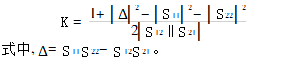
If K>1 and |Δ|<1, the circuit is absolutely stable to any source and load impedance; if K<1 or |Δ|>1, the circuit is potentially unstable [3]. Self-excitation occurs for some sources or load impedance. This does not mean that the circuit does not work, but the signal source and load impedance must be carefully selected. Therefore, when designing the circuit, it is necessary to measure the S parameters of the relevant components.
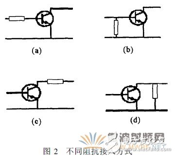
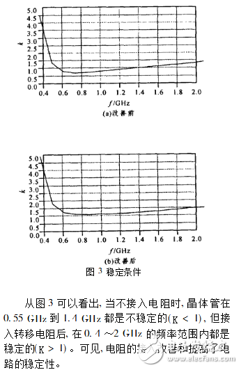
To improve the stability of the circuit, four impedance connections are usually used, and the connection is as shown in FIG. 2. The circuit in Figure 2(b) is connected to a input resistor at the input of the circuit to improve stability. The kf characteristics before and after ADS simulation improvement are shown in Figure 3 (where k represents the stability factor).
Commutators For Industrial Motors
Commutators For Industrial Motors,Commutator For Fan Motors,Commutator For Switching Motors,Commutator For Auto
ZHEJIANG JIAGU ELECTRIC APPLIANCES CO. LTD , https://www.chinajiagu.com