It is well known that semiconductor materials are greatly affected by ambient temperature during operation. High-power LEDs have lower photoelectric conversion efficiency, and only 10% to 25% of the electrical energy is converted into light energy during the work process, and the rest are almost converted into heat energy. In addition, the headlights of the car are installed in the hot engine compartment, and the heat generated by the high temperature water tank, engine and exhaust system places the LED headlights in a harsh environment. Conventional headlight bulbs generate much more heat than LEDs, but the brightness of the bulb output does not change due to heat. The focus of thermal design is on the uniform temperature design inside the housing. The light output of the LED will affect its own PN junction temperature stability due to its own heat or high temperature from the engine compartment. The important parameters such as LED luminous flux ФV and wavelength are directly affected by the PN junction temperature. This poor temperature cycle will cause luminescence. Efficiency and longevity have fallen dramatically. Therefore, heat dissipation has become an important issue in the design of LEDs as a light source.
1. Cooling technology of car headlights
1.1 Passive cooling and active cooling
In the usual heat dissipation design, the circuit board on which the high-power LED is soldered is tightly fixed to the heat sink. The heat generated by the LEDs is conducted through conduction through the circuit board to the aluminum heat sink with better thermal conductivity. The fins of the aluminum heat sink are in contact with the air in a large area to dissipate the heat. In order to effectively reduce the thermal resistance between the heat sink and the circuit board, a heat conductive medium is filled therebetween. The selected radiator has a fin shape and area that can meet the design of the LED headlight cooling solution. This type of heat dissipation is called passive heat dissipation [2].
Active cooling is commonly used in liquid cooling, heat pipe, and air cooling. Since the liquid used for liquid cooling must be forced to take away the heat of the radiator under the driving of the pump, the heat pipe transfers heat by evaporation and condensation of the liquid in the fully enclosed vacuum tube by the heat transfer element with high thermal conductivity, neither of which Suitable for use in car lights. Air-cooled heat dissipation is most commonly used because of its low price and simple installation. For the case where the temperature in the central area of ​​the radiator is relatively concentrated due to the passive heat dissipation method, after the forced convection of the fan is added (see Fig. 1), the temperature unevenness of the radiator is obviously relieved.
1.2 LED heat dissipation channel design
Figure 1: Forced convection after adding a fan
Usually, the LED is soldered on the printed circuit board (PCB) of the double-sided copper layer [1], and the bottom surface of the LED is soldered to the copper surface of the PCB. In order to improve the heat dissipation efficiency, a large copper layer is used as a heat dissipation surface. . This is the simplest heat dissipation structure [3].
The LED for automotive headlamps studied in this paper is a LEUMD1W4 [3] of OSRAM's current maximum power; the die heat dissipation design uses a LE3S package that is more conducive to heat dissipation [1]. The package is characterized by a large copper alloy thermal pad as the base and the die is fixed in the center of the base. At the same time, the insulating medium of the contact area between the LED base and the aluminum substrate is peeled off, so that the copper alloy base is in direct contact with the aluminum substrate. The heat on the pedestal is conducted directly to the outside of the LED. This internal structure removes the dielectric between the die and the pedestal to reduce thermal resistance and more directly derive the junction temperature of the die (see Figure 2a).
Figure 2: L ED, equivalent thermal resistance heat dissipation path for car headlights (click on image to enlarge)
Medical Aid Equipment Wire Harness
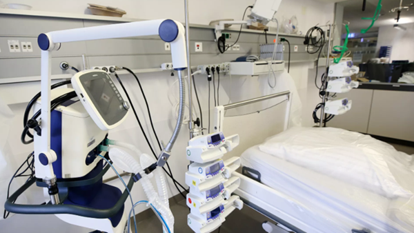
The wiring harness for medical rescue equipment refers to the wiring harness applied to various medical rescue equipment. Emergency medical equipment, that is, the medical equipment used in emergency treatment, refers to the emergency medical equipment used by the rescuer when any accident or emergency occurs.
Before arrival, in accordance with the principles of medical care, use on-site applicable medical equipment to temporarily and appropriately perform preliminary rescue and care for the wounded and sick.
Kable-X provides various connecting harness components for medical device maple equipment. These wiring harness not only meet the needs of signal transmission and high-voltage contacts, electrical appliances and machinery, but also provide reliable and stable quality for customers' special application requirements, most of which are used for Computer tomography equipment, movable auxiliary equipment, solutions for increasing demand, medical electronic beds, rotatable chairs and wheelchair controllers.
We produce a large number of Medical Cable Assembly, including Ventilator Wire Harness, Medical Defibrillator Wire Harness and Medical Aid Equipment Wire Harness .

Medical Aid Equipment Wire Harness,Medical Equipment Wire Harness,Medical Custom Cable Harness,Medical Aid Equipment Wire Harness For Sale
Kable-X Technology (Suzhou) Co., Ltd , https://www.kable-x-tech.com