I. Introduction
At present, all countries in the world are advancing new military changes and realizing a transition from mechanization to informationization. The enhancement of the country’s overall national strength and the deepening of reform and opening up have provided development conditions for the logistic informationization of the Armed Police Force. The heavy workload of the Armed Police Force, namely the "convenience" and "stability maintenance," have raised new and higher requirements for logistic information construction. At present, under the correct leadership of the party committee of the headquarters of the armed police, the construction of logistic information in the armed police force has already done some useful explorations and achieved gratifying results, laying a solid foundation for the successful completion of various tasks by the military.
The Armed Police Force Transport Integrated Management Information System has achieved initial success. With the application of advanced technologies such as global satellite positioning system, global mobile communication technology and geographic information system, the transport security task of the Armed Police Force will be gradually realized. (Three links: data Pass, language pass, image). In the Armed Police Force Transportation Integrated Management Information System, the vehicle monitoring and positioning subsystem is the most important component, and the vehicle's monitoring and positioning are inseparable from the relevant information of the on-board GPS terminal. In the design of the entire system, the design of the vehicle terminal is The most important part. Now the Armed Police Force’s vehicles have been equipped with a considerable number of on-board GPS terminals. However, the system is running well and the information is in circulation. Whether people at all levels can get relevant information in time depends largely on the design of the onboard terminals. Now. This article has improved the design of the on-board GPS terminal of the Armed Police Force and improved its effectiveness to some extent.
Second, the car GPS terminal improved design
In the conventional center-determined vehicle navigation system, most of the vehicle-mounted terminals do not have map data. This saves a certain amount of storage resources and computing resources, but it also brings inconvenience to the driver, especially in real-time path planning. Path planning can only be performed at the monitoring center. For example, Yan Guanghui and Meng Jie in “Research and Design of Cargo Dynamic Tracking Management Information System Based on 3Gâ€, Wang Meng, Yang Xiaoyun, Zhou Jianhe, Zhang Zengfang, “GPS/GIS-based vehicle positioning system designâ€, etc. , Vehicle terminals use the main controller to control GPS receivers, GSM wireless communication modules, hidden alarm options, liquid crystal display and other components; Pan Yi, Chen Xiaoyu in the "GPS/GSM/GIS-based public security private wireless tracking system", Zhan Zhanqiang, Cai Shaohua in "Vehicle Navigation and Monitoring System Based on GPRS/GPS/GIS", etc. Although microprocessors are used, their graphic display functions and calculation processing capabilities are greatly limited, making map matching and paths There is no way to talk about planning.
For the Armed Police Force’s pilots, the process of carrying out the task is a complex and ever-changing process. There are many variables in this process, and many times it is still in the field. The driver’s situation on the road is not very clear. Their There is only one goal. It is to reach the destination safely and in a timely manner. In the "convenience" and rescue mission, it can be said that time is the fighting power of the troops and time is the lifeline. It is extremely important for the driver and the army to complete the mission to plan the driving route in time. In the previous center-determined vehicle navigation system, when the driver needs to change the driving route and seek the optimal route, he must send a request to the monitoring center through the GSM network. After the monitoring center obtains the real-time location of the vehicle, it One-step driving routes are planned, and then fed back to the driver via the GSM network in the form of short messages. This process is cumbersome, especially when the network is congested and the monitoring center is busy. It is easy to cause information delays, loss, and errors. This is inconsistent with the urgency of the time requirements for the implementation of the mission of the Armed Police Force. Therefore, when designing a vehicle-mounted GPS terminal, this paper applies the latest embedded computer technology, adopts a navigation computer design scheme based on the Windows CE operating system, has powerful graphic display functions and calculation processing capabilities, and is small in size, low in power consumption, and reliable. High-quality, powerful development platform, rich sharing software resources, and multiple hardware driver support can fully meet the special requirements of various environments.
For the above requirements, the vehicle navigation system studied here should have the following functions:
(1) The system can determine the real-time position of the vehicle in more than 90% of the travel time, and the deviation from the actual position should be less than 20m;
(2) The system can convert the real-time position of the vehicle into the map coordinates and the road network to provide the most possible road segment of the vehicle in the road network and the position of the vehicle in the road segment;
(3) The system can provide the driver with a graphical real-time vehicle location display with a map as a background;
(4) The system can accept the mission destination request and give the best route to the destination from the current location or designated location according to the appropriate planning criteria;
(5) The system can generate real-time driving guidance instructions according to the planned driving route, and provide the driver with graphical indications or voice prompts;
(6) The system can determine whether the vehicle has deviated from the pre-determined driving route and processed it in time, or alerted the driver in voice or graphical manner, or re-planned the driving route from the current position.
(I) Hardware Design of Vehicle Terminals
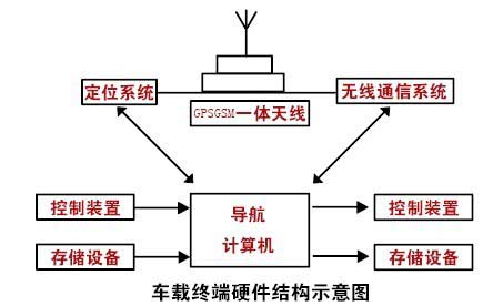
The navigation computer is the core part of the navigation system hardware system. In addition to positioning and communication, the other function modules of the system are based on the navigation computer as the hardware platform, through the application software; the user's operation and control of the entire system also through the navigation computer. carry out. The hardware structure of the system is shown in the figure below.
The navigation computer must have sufficient computing power, basic multimedia functions, strong control and communication capabilities, and good expandability. It must also have good seismic performance. In order to achieve the above requirements, this article has adopted the embedded navigation computer system design scheme in the vehicle navigation system, as shown in the following figure.
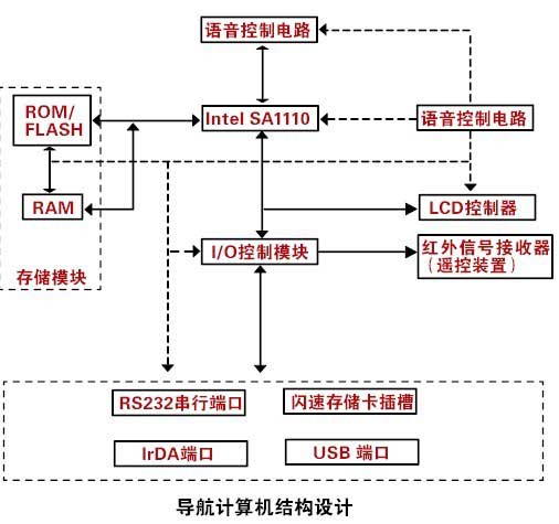
Compared with the traditional computer system, the embedded system removes the support for a large number of unnecessary industrial bus standards, and therefore has fewer components and a more compact structure. The central processor chose the Intel SA1110 Reduced Instruction (RISC) chip with a clock frequency of 206 MHz and a powerful computing power equivalent to a 133 MHz Pentium processor. The processor has built-in functional circuits such as voice coding and decoding, communication protocols, and port control, which can be completed with a small number of peripheral circuits. There are two types of memory devices used in the system: RAM (Random Memory) and ROM/FLASH (Read Only Memory/Flash Memory). The former is used to load and run applications while the system is working, and the latter is used to save programs and data. Since there is no storage device such as a hard disk and a CD-ROM drive that reads data by a fast moving mechanism, the system's ability to withstand earthquakes is greatly increased. In order to strengthen the graphic display function, the system is equipped with a special LCD control circuit and supports 16-bit true color display mode. Taking into account the need for expansion of functions and communication with other devices, the system is equipped with a serial communication port, an infrared data (IrDA) port, a flash memory card (Compact Flash Card) slot and a universal serial Bus (USB) interface. Digital map data is stored on the memory card and is very convenient to replace. In order to strengthen the control of power consumption, a specially designed power management module in the system is responsible for power supply control of the central processor, memory modules, I/O devices, and LCD power supplies. The system uses a button-type infrared remote controller as an input device for user commands and data, and also has a touch panel on the LCD screen.
(B) Software System Design
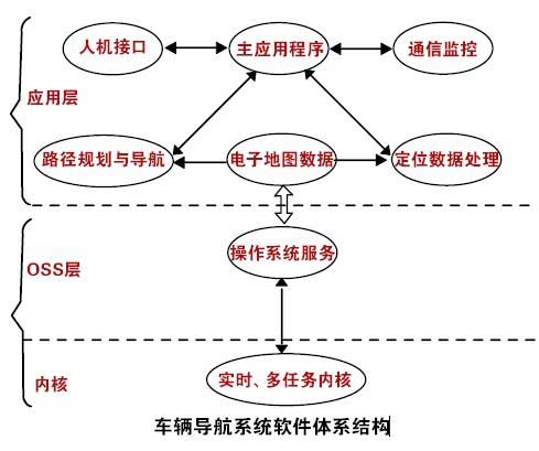
According to the requirements of the system function, the software system of this navigation system can be divided into the hierarchy as shown in the figure below. The operating system is composed of a kernel layer and a system service layer, providing operational support for application software. To meet the needs of real-time processing, the operating system should support multitasking, which allows multiple independent applications to run simultaneously. The kernel refers to the part of the operating system that directly interacts with the hardware and is mainly composed of hardware drivers. It is the only part related to the specific hardware in the entire software system. The system service (OSS) layer is between the application layer and the kernel. It provides basic operating system services such as task creation, memory allocation, disk read/write buffer creation and management, message queue creation, task cycle initiation, and event monitoring to the application layer. . The main functions of the navigation system such as positioning data processing, path planning and navigation, and digital map database operations are all completed by corresponding application layer software modules.
The use of a hierarchical structure in the software architecture makes the application layer software hardware-independent, ie does not depend on the independence of the specific hardware. This irrelevance has two meanings: First, all hardware devices in the system are taken over by the operating system, applications do not directly access the hardware; second, all operations involving hardware are done by calling standard APIs (applications). Interface) function to complete. Hardware independence greatly enhances the portability of applications, and brings convenience to the system's hardware and software development, upgrade, and improvement.
We have been helping customers to complete the research and development and production of various types of battery protection boards, sourcing from around the world, creating the best supply chain system, and using high-precision surface mount technology to achieve product engineering and manufacturing services for high-end and high-quality customers.
BMS,BMS Battery Board,Solar Battery Board,Solar Cell Protection Plate,Battery Board Design
Huizhou Liandajin Electronic Co., Ltd , https://www.ldjcircuitboard.com