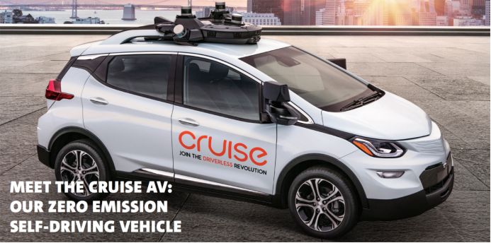
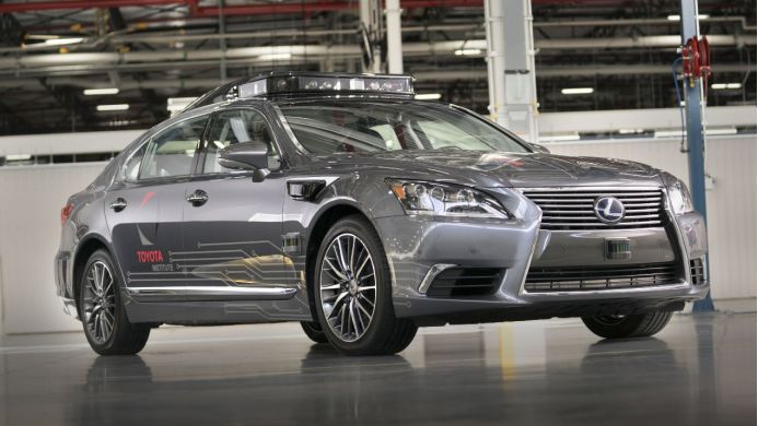
GM released the General Unmanned Vehicle Safety Report on January 13, 2018, and announced that it will mass produce unmanned vehicles based on Bolt pure electric vehicles in 2019. This article will make some analysis and estimates of the general unmanned vehicles based on public information. There may be errors, for your reference only.
The GM's unmanned vehicles don't have a steering wheel and pedals. Obviously, it is impossible to intervene manually, and it also shows GM's confidence in its own unmanned vehicle technology. At the same time, it also shows that traditional car companies have strong competitiveness in the field of unmanned vehicles. If Google wants to do similar unmanned vehicles, then Google must turn to Fiat Chrysler FCA for its customization. This is the embarrassing situation of new car manufacturers or IT autopilot companies. They don't cooperate with traditional car companies. They can't get a relatively good conversion platform. The algorithm can't be strong enough.
Emerging car manufacturers or IT autopilot companies can't get the support of excellent auto manufacturers, because excellent auto manufacturers regard them as competitors and will only try their best to suppress them. Only non-mainstream car manufacturers do not regard emerging car companies or IT autopilot companies as competitors, and at the same time, in order to digest excess capacity, they are willing to cooperate with new car manufacturers or IT autopilot companies. Another embarrassing thing is Tesla. Although it only reaches the L2 in the SAE classification, it is promoted to L4, and it is in the limelight. However, the technical strength is insufficient. L2 is L2 after all, L3 of Audi A8 and L5 of General Cruise (also not fully achieved by L5 of SAE, more suitable for L4+), which surpasses Tesla in practical application and publicity.
Model 3 has not reached expectations, and Tesla expects to deliver 2,917 new Model 3 vehicles in the fourth quarter of 2017, but only 1550 vehicles were actually delivered, and only 517 vehicles were delivered in December. As a competitor of Model 3, GM's Bolt sales continued to climb, with 1971 sales in July and 3,747 in November. Sales in December reached 3,327, a nearly five-fold increase from the previous year, six times that of Model 3. With annual sales exceeding 23,000 units, capacity is not a problem for GM, and the capacity of 30,000 units per month can be easily achieved.
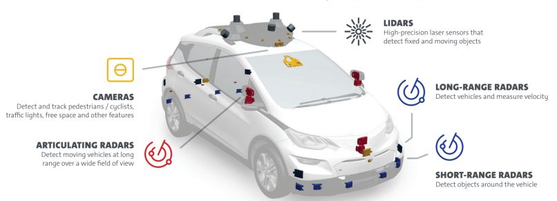
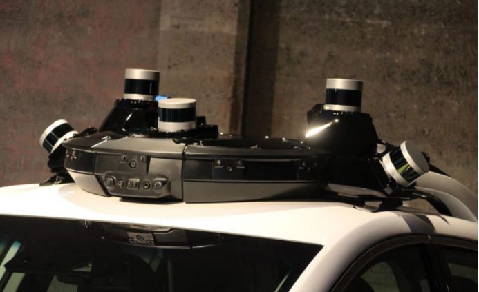
The GM's unmanned vehicle uses five laser radars, 21 millimeter-wave radars and 16 cameras. The five laser radars are Velodyne's VLP16 16-line laser radar. In early January of this year, Velodyne lowered the price of VLP16 from $7,999 to $3,999. Baidu and Ford, as the major shareholders of Velodyne, can make GM money. Twelve 79 GHz millimeter-wave radars in 21 millimeter-wave radars are provided by Japan's ALPS. Two forward two backward long-range millimeter-wave radars are speculated by the German mainland. The model may be ARS-408. Five high resolutions (general purpose) It is called "Articulating". The millimeter wave radar is provided by Bosch in Germany, mainly on both sides and in front of the car.
Among the 16 cameras, 10 roofs, including a binocular camera with a base length of about 8 cm, 8 360-degree surround cameras, infrared LEDs around the camera, can work in low illumination or even dark night, of course, the ratio will drop. a lot of. There is a non-driving version of Bolt's monocular camera in the interior rear view mirror, and a long-distance monocular camera at the front of the vehicle. Two exterior cameras and two cameras at the rear of the car.
Lidar application
The general text is We start with LiDAR, which provides highly precise feedback using laser measurements for both fixed and moving objects. Lidar is first positioned, the first step of the unmanned vehicle is also positioning, using the lidar detection of the laser radar SLAM or with the global Maps do match, and then achieve centimeter-level positioning, which is consistent in the industry, Baidu, Google and general mainstream manufacturers are the same. Most of the non-mainstream manufacturers use GPS RTK positioning. There are two very conspicuous mushroom antennas. GPS RTK positioning can not be used for large-scale applications, and can only be used to pull investment demos.
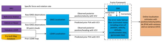
The picture above shows the Baidu unmanned vehicle positioning frame. The disadvantage of this positioning method is that it is necessary to make a lidar map in advance, which is the Prior LIDAR MAP, which is not difficult for GM. GM has produced laser maps of all highways in the United States in its super cruise. However, if there is no area for making lidar maps in advance (such as the vast suburbs and rural areas with sparsely populated areas), the unmanned vehicles can't do centimeter-level positioning, and only the traditional GPS can be positioned up to 3 meters.
The second role of the lidar is to combine the camera data to achieve target classification and trajectory tracking. The general text is like this: We combine LiDAR and camera data for classifying and tracking objects, making high confidence determinations more quickly. This helps, for Example, identify pedestrians, vehicle types and road details such as lane lines, construction zones and signage. It is speculated that the laser radars from both sides are used to obtain road details such as lane lines, roadsides, isolation belts, virtual solid lines, and zebra crossings. Baidu unmanned vehicles also use Lidar to obtain road details. Jingchi, who was born in Baidu, demonstrated the technology of identifying lane lines, pedestrians and vehicles using only lidar at 2018 CES. The same is true for Google and Toyota.
At present, there are four main methods for detecting the lane line by Lidar. One is based on the echo width of the laser radar. The second is a grayscale map formed according to the information of the laser radar reflection intensity, or the invalid information is filtered according to the intensity information and the elevation information. Third, the Lidar SLAM cooperates with high-precision maps to detect not only lane lines but also self-vehicle positioning. The fourth is to use laser radar to obtain different characteristics of road edge height information or physical reflection information, first detect the road edge, because the road width is known, and then calculate the lane line position according to the distance. This method cannot be used for roads where the road edge and the road height differ by less than 3 cm. The latter three methods require multi-line lidar, and at least 16-line lidar. The former can use 4-wire or single-line lidar. Most of the current methods are based on the second method. The sign of this method is that the laser radar needs to be as close as possible to the road surface or toward the road surface to obtain more reflection intensity information. Toyota and Google both place laser radar on the front bumper of the car. The general purpose is that there are 9 millimeter waves near the bumper. The radar and a camera are estimated to be insufficiently installed and can only be placed on the roof.
The fusion of the lidar and camera data directly in front of the middle can increase the speed and accuracy of identifying the target. There are two ways to identify targets with lidar. One is to use the value of the laser radar reflection intensity. The different characteristics of the material have a great difference in the intensity of the lidar reflection. This difference can be used to easily classify the target, such as pedestrians, vehicles, buildings. , plants, roads, grass, etc. Because it is a simple threshold filter, the amount of calculation is small and the speed is very fast, much higher than the target classification of deep learning. In early January 2018, Renesas announced a partnership with startup Dibotics, which has an enhanced laser radar (Augmented LiDAR) software that uses this method for classification and identification, and Renesas will embed the software into its chips. The second is to convert the lidar's point cloud into dense image data with a tensor structure and then identify it with the fast RCNN. The latter requires powerful computing resources and the processing speed is relatively slow. Faster RCNN is the best recognized method in the field of image recognition. It is speculated that the former is used in general, and the deep learning recognition of the camera should be based on the fast RCNN.
Another advantage of Lidar is that it is good at predicting the trajectory and trajectory tracking of moving objects, which is the basis of behavioral decision-making. Just like a human driver, you can estimate the direction or position of a pedestrian or other vehicle in the next step and make a decision based on this estimate. Laser radar is inherently capable of trajectory-yielding, and Velodyne's 16-line lidar accurately predicts the movement of the ball after the quarterback in the most powerful Super Bowl event in the United States (A Velodyne VLP-16 LiDAR read off) Each tossed football's speed and direction to predict where the ball would land). Velodyne is very proud of this. Therefore, GM also uses lidar tracking objects, which is much faster than the camera using the optical flow method to calculate the trajectory and predict, and the computing resource consumption is far lower than the optical flow method.
Millimeter wave radar application
In the United States, if you want to use a wireless device that is not FCC certified, you must first apply for a temporary license (STA), otherwise it is illegal. On March 17, 2017, Japanese automotive electronics supplier Alps Electric applied for a STA license, and Alps Electric was testing a vehicle-based millimeter-wave radar called Ukaza, which operates in the 76-81 GHz band. This is the first public test of the millimeter-wave radar in this band. In the application, Alps Electric said that the company wants to test 3,000 Ukazas from May 1st. The Alps means that each vehicle needs to be equipped with 10 sets of radars, so 3,000 Ukazas are only available for 300 vehicles. Ten days later, GM also submitted a similar STA license application to the FCC, which is also testing the Ukaza radar. However, General Engineer Robert Reagan asked the FCC to help keep confidential in the application because the test involved business sensitive information. Obviously, ALPS's millimeter-wave radar is used in General Motors, which is the 300 unmanned test fleet that GM has to build.
The Ukaza radar is not the only equipment for Bolt. On March 28th (one day after the general application), Bosch also submitted its own STA license application. The Bosch application stated that the company was to test mid-range radar (77 GHz) in the customer's autonomous fleet and subsequently develop new algorithms from the collected data. From the application point of view, Bosch has to test a total of 650 radars, enough for 162 vehicles. There are four cars per car. Similar to the Alps company, Bosch did not name the customer, but gave the test the specific location. From the latitude and longitude, these radars will be tested in San Francisco, Detroit and Scottsdale. The only company that tests across the three places is the GM.
After a few months of testing, GM may not feel enough, so the number has increased, the number of 79GHz has increased to 12, and the high-resolution (commonly known as Articulating) millimeter-wave radar has increased to five. If Bosch's radar is a traditional 77GHz millimeter-wave radar, there should be no need to propose a STA to the FCC. It is speculated that it may be a 2-4GHz bandwidth radar. It is also possible that Bosch will call the 76-81GHz radar (also known as the 79GHz radar) a 77GHz radar. Bosch can't make radar transceivers. It is also very likely to be a 79 GHz radar. Its bandwidth is up to 8 times that of the traditional 77 GHz radar, so the resolution is up to 4 cm. It is also known as Articulating.
The 12 79GHz millimeter-wave radars operate in cascade mode, which is sufficient for the millimeter-wave radar to present a clear 360-degree panoramic image and to track thousands of targets simultaneously. It is speculated that the 12 79 GHz millimeter wave radars are redundant systems. The millimeter wave radar has the strongest ability to cope with complex environments. It is most suitable for redundant systems. In the case of laser radar and camera failure, it is still safe to drive to the roadside parking. .
NXP introduced the MR3003 and S32R274 on January 11th, 2018. It is a typical cascade design. The MR3003 is a 3/4 receiver millimeter wave radar transceiver. The NXP cascade design is cascading 4 MR3003, up to 12 Send 16 and receive the processor from S32R274, which can support up to 20 MR3003 cascades, reaching an amazing 60-80 80-mm radar, which is enough for imaging.
The so-called cascading is actually similar to MIMO. Multiple input multiple output (MIMO) was originally a concept in the control system, indicating that a system has multiple inputs and multiple outputs. If the transmission channel of the mobile communication system is regarded as a system, the transmission signal can be regarded as an input signal of the mobile channel (system), and the reception signal can be regarded as an output signal of the mobile channel. The basic meaning of MIMO radar is that the radar uses multiple transmitting antennas, simultaneously transmits mutually orthogonal signals, illuminates the target, and then receives the target echo signals with multiple receiving antennas and performs comprehensive processing to extract the spatial position of the target. And information such as the state of motion.
A typical application of the MIMO radar virtual array is for radar two-dimensional imaging. The range resolution of radar two-dimensional imaging mainly depends on the bandwidth of the radar signal, and the azimuth resolution mainly depends on the beam width of the antenna. To increase the distance resolution of imaging, it is relatively easy to increase the bandwidth of the radar signal. In order to improve the azimuth resolution of the radar signal, it is necessary to increase the aperture of the antenna or the array, which is limited by many factors in practice, and is very difficult. The widely adopted solution is to use synthetic aperture technology to obtain a large aperture array without increasing the physical size of the antenna. Different from the idea of ​​synthetic aperture, MIMO radar is equivalent to form a virtual large aperture array by using multiple antenna antenna structures to obtain high resolution in azimuth. The formation of this virtual array is real-time, which can avoid the motion compensation problem existing in the traditional ISAR imaging. Therefore, MIMO radar has its unique advantages in imaging applications.
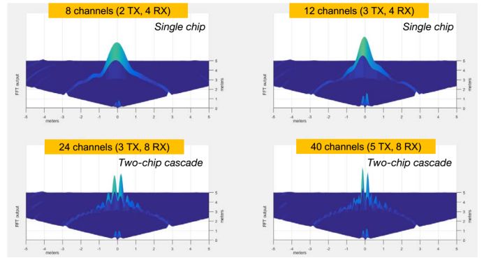
The above picture shows the FFT output of a multi-chip cascade radar (MIMO) tested by Texas Instruments. It is obvious that the more channels, the higher the level of sophistication.
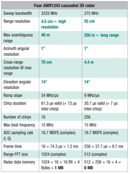
The above table shows the parameters of the four AWR1243 cascaded radars of Texas Instruments. The long-distance resolution is greatly improved. The azimuth resolution of 1 degree can be achieved at 40 meters, which is the accuracy of 4.5 cm and the separation accuracy of objects of about 9 cm. . In the case of a megapixel 45-degree FOV camera, there is only about 20 pixels of azimuth resolution at 40 meters, making it impossible to distinguish between pedestrians and cyclists. MIMO has a wide FOV, and the four cascaded radar FOVs like Texas Instruments are up to 192 degrees. The 80 degree FOV of the camera is a wide angle, and there may be wide-angle distortion at the edges.
A pair of transmitting array elements and receiving array elements can virtualize a transmitting and receiving array element. For a MIMO radar with M-output N, the transmitting array element and the receiving array element have a total of M*N pairs, that is, the M*N transceiver array can be virtualized. The number of elements is generally much larger than N, thus realizing the expansion of the array aperture.
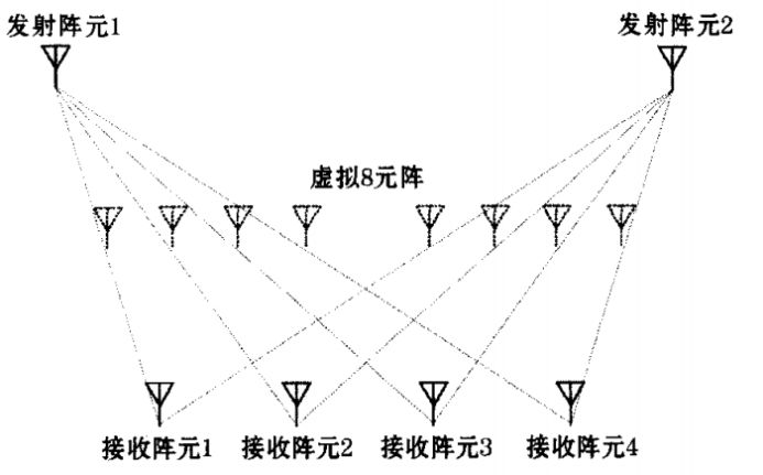
Texas Instruments uses four ASR1243 radars with three outputs and four receivers, which are 192 virtual channels (antennas or arrays).
Camera application
In terms of autonomous navigation partial path planning, according to the general description, GM seems to use the Free Space method, which is the biggest difference between GM and Baidu and Google. Both Baidu and Google use the grid method. The grid method is currently the most widely used and most reliable partial path planning. It is made by w. E. Howden was proposed in 1968. The grid method decomposes the robot working environment into a series of grid cells with binary information. The position and size of the obstacles in the workspace are consistent, and the position and size of the obstacles do not change during the robot movement. The two-dimensional workspace of the robot is divided by a grid of the same size, and the size of the grid is based on the size of the robot itself. If there is no obstacle in a grid range, the grid is called a free grid; otherwise, it is called a barrier grid. Free space and obstacles can be represented as integration of grid blocks. There are two ways to identify the grid: the Cartesian coordinate method and the serial number method. The working environment is represented by a quadtree or an octree, and the path search is completed by an optimization algorithm. The method records environmental information in units of grids. The smaller the grid granularity, the more accurate the representation of obstacles, but at the same time it will occupy a large amount of storage space. The search range of the algorithm will increase exponentially and consume a lot of computing resources. This method is generally matched with a 64-wire mechanical rotating laser radar. The higher the number of lines, the smaller the granularity. So there will be 12 16-line laser radars of 128-line lidar and Apple, and there may be 256-line lidar in the future. The overall cost is too high is the main drawback of the grid method.
The free space method constructs a free space using pre-defined basic shapes such as generalized cones and convex polygons, and expresses the free space as a connected graph, and performs path planning by searching for connected graphs. The construction method of free space is: starting from one vertex of the obstacle, sequentially making the link lines of other vertices, deleting unnecessary link lines, so that each free space enclosed by the boundary of the link and the obstacle is the largest area. Convex polygon: The network diagram formed by connecting the midpoints of each link line is the route that the robot can move freely. The advantage is that it is more flexible, and the change of the starting point and the target point does not cause the reconstruction of the connected graph. The disadvantage is that the complexity is proportional to the number of obstacles, and sometimes the shortest path cannot be obtained. The segmentation of the free space method needs to construct the imaginary boundary, and the imaginary boundary itself has arbitrariness, which leads to the uncertainty of the path.
The advantage of the free space method is that it does not need to use high-line laser radar, it can be used for single-eye, and the computing resource consumption is also small. The disadvantage is that the reliability is not high, sometimes the path planning cannot be obtained, and temporary stagnation may occur, or the road may be detoured. The most important point is that it is very sensitive to light. In the avenue under the sun, the sun shines directly on the camera, and the low-light environment can't be used in rain, snow and fog. General use of laser radar to make up for some of the shortcomings, while adding infrared LEDs around the camera to increase the ability to adapt to low illumination environment. At the same time, the effective distance is relatively close, and the speed of the vehicle is usually not higher than 100 kilometers per hour. Intel and the Mobileye camp favor this approach.
The camera at the universal logo should be the main camera. It is very likely to use Sony's IMX390CQV sensor. This is a 1/2.7 CMOS sensor with an effective pixel of 2.45 million. It is the highest pixel image sensor in the world. The IMX324 image sensor released in October 2017 has better performance and is the world's best image sensor with the best performance and effective distance (error less than 5%). However, samples will be available at the end of 2017. Not used. The IMX324 is a 1/1.7-type CMOS image sensor with 7.42 million industry's most effective resolution RCCC filters. With the help of a FOV 32° lens, it can shoot road signs 160 meters away from the camera. The sensors developed by EyeQ4 and EyeQ5 are extremely expensive. However, even in narrow lenses (35 degrees below the narrow viewing angle, usually the car's front lens is 45 degrees), the effective distance is only 160 meters, if it is 45 degrees, the effective distance is 150 meters. The IMX390, with a 45-degree viewing angle, estimates an effective distance of 65-75 meters. The 64-line laser radar can do 200 meters. However, the speed of electric vehicles in urban areas is not high.
The universal binocular camera has a baseline distance of approximately 8 cm and a short effective distance of only 10-12 meters, which should be used primarily to identify pedestrians and cyclists. Using binoculars to quickly identify pedestrians and cyclists, Mercedes-Benz and BMW have been heavily used in the car, which is a relatively mature technology. This technology is of course not related to deep learning. The biggest disadvantage of deep learning is that it consumes a lot of computing resources, which is inefficient and slow.
This technique is called stixels, sticks above the ground in the image. It refers to modeling the columnar objects above the ground in the picture. Obviously, objects such as trees, people, posters, etc. in the image can be called pillars.
The bottom of the so-called stixels depth information here is the ground, the top, and the approximate location where the top of the pedestrian may appear. For each column in the image, the distance between the bottom pixel, the top pixel, and the unclassified object is estimated. The key to this approach is that stereo images can be used to directly calculate stixel without having to calculate all depth information. In the pedestrian detection, the ground and stixel in the image are estimated, and the height of the stixel is set to 1.75m, and in 2010, the speed can reach 135fps on the CPU. And deep learning can achieve 30fps and you need GTX1080 graphics card. Stixels are at least 20 times faster than deep learning.
The eight cameras on the roof are redundant, and even if the lidar and millimeter wave radars fail, 360-degree panoramic video around the vehicle is still available. The monocular at the rear view mirror is also a redundant system, which is the L2 level AEB emergency brake system.
Computing unit and other
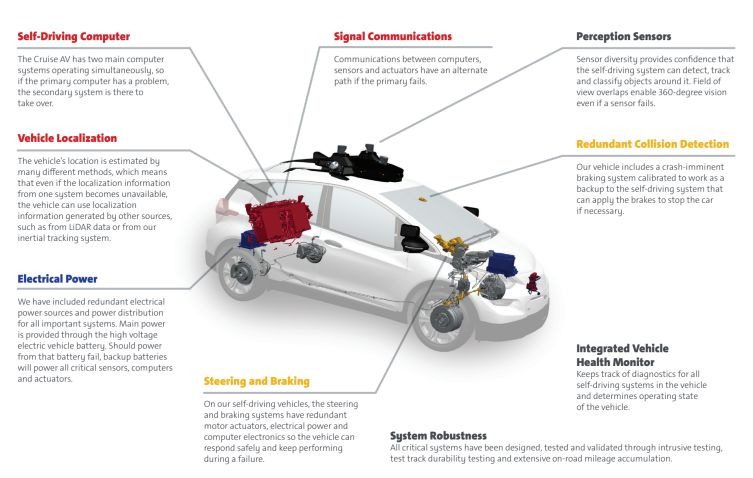
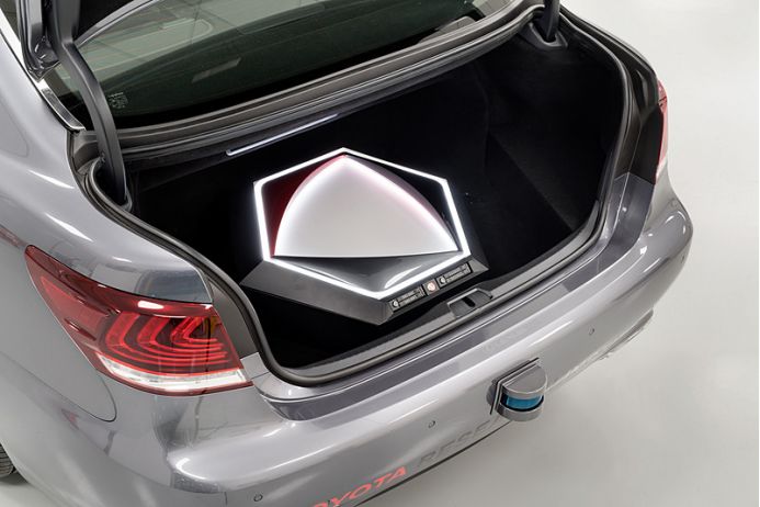
Like Google's unmanned vehicles, the GM's unmanned vehicles also use two computing platforms to ensure that one set fails and the other can run without interruption. The computing platform is located in the trunk and there are also two power supply systems. The main power supply is converted to a high voltage supply by the battery of the electric vehicle itself. Note that GM uses the term high voltage. If it is NVIDIA's DRIVE PX2 or other vehicle-specific computing platform, it should be a low voltage of 3 to 5.5 volts. Therefore, it is speculated that GM does not use NVIDIA's computing platform or other vehicle-specific computing platforms. It is very likely that an industrial computer is used. Usually, the input voltage of the industrial computer is 24 VDC, which is equivalent to 5.5 volts or 12 volts common in the car. If the primary power fails, the backup power is turned on. The backup power supply will supply all sensor units, actuators and arithmetic units.
Andrew Farah, chief engineer of the Universal Unmanned Vehicles, revealed that the backup power supply of the first generation of unmanned vehicles was as high as 3 kW. Be aware that the first generation of unmanned vehicles used only two 32-line lasers, no more than 10 millimeter-wave radars, and no more than five cameras. But Andrew Farah did not disclose the power of the latest generation of unmanned vehicles, the fourth generation of unmanned vehicle backup power, but he insisted that the power is reduced, it is estimated that it may reach 2 kilowatts. It is certain that the battery life of this electric car will be reduced.
Baidu is a two-pronged approach, one is an industrial computer (using the Needys Nuvo-6108GC, which is a powerful X86 deconstruction industrial control computer); the other is NVIDIA's Drive PX2 for autonomous driving.
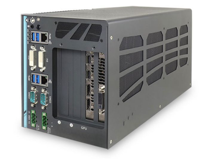
Nuvo-6108GC is the industrial computer of Taiwan's 宸曜 technology, using ASUS GTX 1080 GPU graphics card, Intel dual Xeon E5-2658 V3 12-core CPU, 1TB 2.5-inch 7200 rpm SATA hard drive (saving point, no solid state).
It is speculated that GM uses the main energy in algorithms and sensors. The computing platform does not cost much energy. In the future, it will definitely be replaced by a low-power embedded system. Most likely, it is two or four Renesas R-CAR. H3 is used in parallel, and R-CAR H3 is the world's most powerful car-class SoC. The cost can be greatly reduced by then.
The other parts of the universal unmanned vehicle, the battery, the motor and the electronic control part are supplied by LG Korea. The brake actuator is Bosch's second-generation iBooster. The ESP is also Bosch. The steering system may be the Nexteer NEXTEER of the AVIC Group. Supply, camera module may be provided by Magna, Canada.
Analysts at Morgan Stanley expect the cost of the GM Bolt unmanned vehicle to be as high as $25-300,000, which I expect may not be as high, but at least $150,000. Obviously this is not possible for the general consumer market. Only the taxi, shared travel or online car market is not sensitive to the cost of car purchase, and the field with high sensitivity to labor costs is the main market for unmanned vehicles.
On the whole, the technical level of the universal unmanned vehicle is still lower than that of Google, even lower than Baidu, but the general commercialization process will be much faster than Google and Baidu. The technology gap between traditional car companies and IT companies in the field of unmanned vehicles is rapidly shrinking, and the commercialization process of traditional car companies is much faster than IT companies as long as they are determined.
Pictured above is Toyota's third-generation unmanned vehicle, which replaces the 64-line mechanically-rotating laser radar of the original roof with four solid-state laser radars.
The picture above shows the computing unit of the Toyota Unmanned Vehicle. It can be seen very compact and extremely complete. This is the most technologically advanced and complete unmanned vehicle, much higher than Google. Once the traditional auto giants are launching unmanned vehicles, IT companies will no longer have an advantage.
Antenk mini usb:The small USB socket found on digital cameras, external hard drives, USB hubs and other equipment. Mini USB is much smaller than USB Type A and B but twice as thick as Micro USB (see illustration below).
MINI USB, also known as Mini USB, is a USB interface standard. USB is the abbreviation of universal serial bus in English, which means "universal serial bus" in Chinese. It is a technology developed for data transmission between PC and digital devices. Standard USB, MINIUSB and microusb have become the most common USB interfaces. Compared with standard USB, MINIUSB is smaller and suitable for small electronic devices such as mobile devices.
Mini USB is divided into a type, B type and ab type. Minib type 5pin interface is the most common interface. Due to its excellent anti misplug performance and small size, it is gaining the favor of many manufacturers. This interface is widely used in card readers, MP3, digital cameras and mobile hard disks.
Mini USB a, B connectors and their contacts (not drawn to scale) Mini USB Connector contact function
1 VBUS (4.4–5.25 V)
2 D−
3 D+
4 ID
5 grounding
The ID foot is only used in OTG function. The Mini USB interface is divided into mini-a, B and ab interfaces. If your system is only used as a slave, then use the B interface. The system controller will judge the level of the ID pin and determine what kind of device is inserted. If it is Gaoping, it is the B connector. At this time, the system will do slave mode. If the ID is low, it will be a interface. Then the system will use HNP dialogue protocol to decide which is the master and which is the slave
OTG is the abbreviation of on the go, that is, OTG technology is to realize the data transmission between devices without host. It is mainly used in the connection between different devices or mobile devices for data exchange. For example, the digital camera is directly connected to the printer, and through OTG technology, the USB port between two devices is connected to print out the photos taken immediately; the data in the digital camera can also be sent to the mobile hard disk of USB interface through OTG, so there is no need to carry expensive memory card or carry a portable computer for field operation.
Except for pin 4, other interface functions of Mini USB are the same as those of standard USB. The fourth needle becomes the ID, which is connected to the fifth needle on the mini-a, and can be suspended in the mini-b or connected to the fifth needle.
Mini USB
ShenZhen Antenk Electronics Co,Ltd , https://www.antenkconn.com