Today, I will introduce a national invention authorized patent-thermal air flow meter. The patent was applied for by Hitachi Automotive Systems Co., Ltd., and the authorization was announced on April 5, 2017.
Content descriptionThe present invention relates to a thermal air flow meter that measures the flow rate of air. For example, it relates to a thermal air flow meter that is mounted on an intake pipe of an internal combustion engine and measures the flow rate of intake air supplied to the engine.
Background of the inventionA thermal air flow meter that measures the flow rate of intake air supplied to the internal combustion engine is installed and used in a part of the intake system of the internal combustion engine. The thermal air flow meter has, for example, a structure in which a flow detection element such as a heating resistor generates heat to measure the flow rate of the passing air based on the amount of heat dissipation to the air. Therefore, it is necessary to consider protecting the flow detection element and ensuring the accuracy of the flow measurement, so as not to be affected by contaminants under long-term use. In addition, in the intake pipe of an internal combustion engine, the intake air flow rate is arranged to pulsate along with the opening and closing of the intake and exhaust valves of the engine, so that it is necessary to consider intake pulsations such as reverse flow generated when the intake pipe resonates.
Therefore, in a conventional thermal air flow meter used in an internal combustion engine, as described in Patent Document 1, a flow detection element is arranged in the auxiliary air passage to protect the flow detection element from contamination or The impact of backflow and so on. In addition, in recent years, from the aspects of exhaust gas purification and fuel consumption improvement, high-precision measurement of the intake air flow is required, and there is a need for a hot air that can accurately measure the backflow generated in the intake pipe. Flow meter.
Since the thermal air flow meter measures the reverse flow even when the detection element is arranged in the secondary air passage, the secondary air passage of the thermal air flow meter is required to have a complicated structure such as a curved passage portion or a throttle shape. On the other hand, from a market perspective, there is also a demand for lower cost of thermal air flow meters. That is, it is necessary to overcome the opposite problem of realizing cost reduction while requiring a complicated structure.
If the auxiliary air passage is complicated, the number of structural members increases, and there is a proposal to form the auxiliary air passage by combining the above-mentioned structural members. However, increasing the number of components leads to an increase in cost. In order to achieve cost reduction, it is necessary to construct a complicated structure without increasing the number of components. In this way, in addition to reducing component costs, assembly man-hours can also be reduced, so that the cost of the thermal air flow meter can be reduced or the increase in cost can be suppressed.
Summary of the inventionThe present invention was made in view of the above-mentioned aspects, and its object is to provide a thermal air flow meter that suppresses deformation of the base member during molding, ensures dimensional accuracy, and has a small influence on measurement accuracy from dimensional changes, and is capable of measuring air flow with high accuracy.
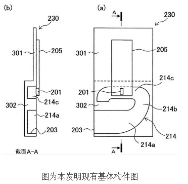
The thermal air flow meter of the present invention that solves the above-mentioned problems has: a housing member arranged in the intake passage of an internal combustion engine; a plate-shaped base member fixed to the housing member and having a device for supplying air through the intake passage Part of the secondary passage that flows in; the flow detection element is arranged in the secondary passage; the circuit board, which is electrically connected to the flow detection element, inputs the heat dissipation of the flow detection element and outputs a signal corresponding to the air flow, the thermal air flow The meter is characterized in that the base member is composed of a synthetic resin material, and has: a substrate fixing part that fixes the circuit substrate; and a sub-channel structure part that is continuous and integral with the front end of the substrate fixing part, and is integrated with the housing The members cooperate to form the sub-channel; the reinforcing structure is provided at least at the connecting portion between the substrate fixing portion and the sub-channel structure portion to improve the strength of the base member.
According to the thermal air flow meter of the present invention, the base member is composed of a synthetic resin material, has a board fixing portion for fixing the circuit board, is formed integrally with the front end portion of the board fixing portion, and is formed by cooperating with the housing member. The sub-channel structure portion of the channel is provided at least at the connection portion between the substrate fixing portion and the sub-channel structure portion to increase the strength of the base member, and the strength of the flat base member is increased by the reinforcing structure.
Therefore, during the molding of the base member, even in the case where the difference in thermal shrinkage between the thin-walled portion and the thick-walled portion is uneven, it is possible to suppress the occurrence of the base member at the boundary between the thick-walled portion and the thin-walled portion. Warp deformation, wherein the base member has a substrate fixing portion composed of a thin-walled portion whose resin thickness is substantially constant, and a sub-path forming portion in which a thick portion is present in order to form the sub-path.
Therefore, it is possible to prevent defects in mounting to the housing member and circuit board due to warpage and deformation, and prevent unevenness in flow measurement accuracy.
We all know that curved-edge phones look good, but they are not easy to protect. In order to prevent the mobile phone from being scratched, current mobile phone users like to stick a phone Screen Protector on the mobile phone screen.
With the development of the market, more and more users like mobile phones with curved screens. Unlike flat mobile phones, the screen protectors of curved screen mobile phones are not easy to buy or stick. The main reason is that the Tempered Glass Screen Protector of curved mobile phones is difficult to fit the height of the mobile phone screen. Then our TUOLI Uv Screen Protector is the best choice for full screen users.
Using the curing principle of the 30 UV lamp beads of the UV Curing Machine to scan the entire screen, the UV Screen Protection Film has the texture of tempered glass. The upper limit of the high temperature of the UV Machine is 60 degrees, has a good heat dissipation function, and has a time setting: 180 seconds. Exquisite and easy to operate, it can make the Screen Protective Film have high light transmittance and smoothness.
Uv Curing Film,Uv Screen Curing Film,Uv Protective Curing Film,Uv Glass Curing Screen Protector
Shenzhen TUOLI Electronic Technology Co., Ltd. , https://www.hydrogelprotectors.com