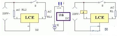
The above figure shows some examples of using LCE devices as control loads to provide creative ideas for the wide range of applications. There are two typical application modes of the LCE module, as shown in (a) and (b). (a) is a wiring diagram that directly drives the AC load using the module. When the switch S of the active load RL1 is closed, current flows through the driven load RL2. (b) is a wiring diagram for controlling other equipment by using the AC relay J (both AC and DC equipment). When the active load RL1 is turned on, the AC relay J is energized and attracted, and the contacts of J are used to control other high and low voltage, AC and DC power devices.
Longkou Libo Insulating Material Co.,Ltd. , https://www.liboinsulation.com