The π-type filter consists of two capacitors and an inductor, both of which have low impedance at both input and output. Π-type filtering is available in RC and LC.
In the case where the output current is not large, RC, R can not be too large, generally several to several tens of ohms, which has the advantage of low cost. The disadvantage is that the resistor consumes some energy and is not as effective as the LC circuit. It is also good to use a larger filter capacitor.
The LC circuit has an inductor that selects the amount of inductance based on the magnitude of the output current and the frequency. The disadvantage is that the inductor is bulky, bulky, and expensive. Now the power of general electronic circuits is RC filtering. Rarely use LC filter circuits.
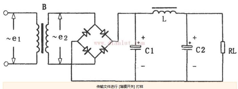
Π-type filter circuit schematicThe function of the filter circuit is to remove unwanted harmonics. In the DC power supply, the ripple of the current is reduced, and the current is smoother. Commonly used are capacitor filter circuit (C), inductor filter circuit (L), capacitor inductor filter circuit (LC), capacitor inductor π-type filter circuit (LCπ type), which are often used in power circuits. Others include electronic filter circuits, etc., which are often used in complex high-precision pulse circuits.
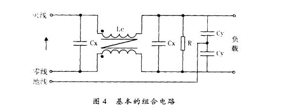
In fact, differential mode interference and common mode interference often exist simultaneously in the power supply. Therefore, the power supply filter circuit generally refers to a total as shown in FIG. Modular and differential mode filtering are combined,
Le is a common mode choke. Since the two coils of the LC are wound in the same direction, when the power input current flows through the LC, the generated magnetic fields can cancel each other and do not cause saturation of the core. Therefore, it uses magnetic permeability. High core. Le is equivalent to a large inductance inductance for common mode noise, so it can effectively suppress common mode conducted noise. The capacitor Cy connected to the ground at the load input side bypasses the common mode noise. The capacitor CX connected in parallel at both ends of the common mode choke coil suppresses the differential mode noise. R is the discharge resistance of CX, which is recommended by the VDE-0806 and IEC-380 safety technical condition standards. The parameter range of each component in the figure: Cx=0.1~2pF; Cy=22~33nF; Le=several~several tens of mH, different parameter values ​​are taken depending on the working current. If the current is 25A, Le = 1, 8mH; the current is 0.3A; Le = 47mH. The choke coil generally uses a high magnetic permeability rod core material, which is very effective for eliminating high frequency interference, but for large working current, the volume of the choke is relatively large to avoid magnetic saturation.
Typical π-type RC filter circuitFigure 7-27 shows a typical 兀-type RC filter circuit. Cl and C2 in the circuit are two filter capacitors, Rl is the filter resistor, and Cl, Rl and C2 form a π-type RC filter circuit. Since this filter circuit is in the form of a letter π and uses a resistor or a capacitor, it is called a π-type RC filter circuit. ADP3211AMNG can be seen from the circuit, the π-type RC filter circuit is connected to the output of the rectifier circuit.
The filtering principle of this circuit is that the voltage output from the rectifier circuit is first filtered by Cl, and most of the AC components are filtered out, as shown in the AC current diagram.
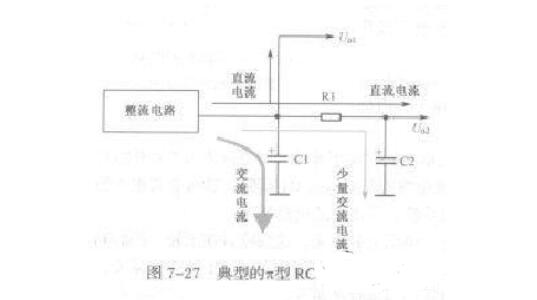
The voltage filtered by Cl is added to the filter circuit composed of R1 and 02. Capacitor C2 further filters the AC component, and a small amount of AC current reaches the ground through C2, as shown by the current in the figure.
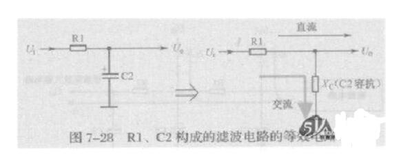
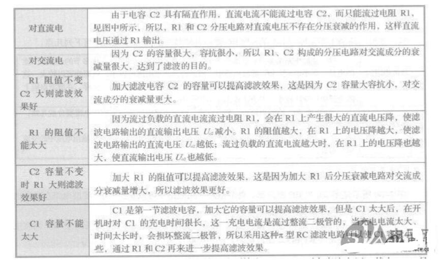
There are two DC voltage output terminals in this filter circuit, which output two DC voltages U01 and U02 respectively. Among them, U01 is only filtered by capacitor Cl; U02 is filtered by Cl, Rl and C2 circuits, so the filtering effect is better, and the AC component in DC output voltage U02 is smaller.
The above two DC output voltages are different in magnitude, and the Uo1 voltage is the highest. Generally, this voltage is directly applied to the power amplifier circuit, or to a circuit that requires the highest DC operating voltage and the largest operating current. This is because the DC output is DC. The voltage does not pass through the filter resistor, and can output the maximum DC voltage and DC current; the DC output voltage U02 is slightly lower, because the resistor R1 has a voltage drop to the DC voltage, and at the same time, due to the existence of the filter resistor R1, the DC output of the filter circuit The magnitude of the current is also limited.
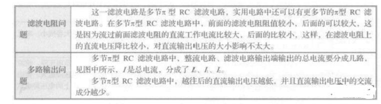
Multi-section π-type RC filter circuitThe practical filter circuit is usually multi-section, that is, there are several π-type RC filter circuits, and the π-type RC filter circuits can be connected in series or in parallel. The multi-section π-type RC filter circuit is also composed of a filter capacitor and a filter resistor. Figure 7-29 shows a multi-section π-type RC filter circuit. In the circuit, Cl, C2, and C3 are three filter capacitors, where Cl is the filter capacitor of the first section, and C3 is the filter capacitor of the last section. Rl and R2 are filter resistors.
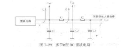
The working principle of this filter circuit is basically the same as that of the above π-type RC filter circuit, and the following points will be described here.
Superfast Recovery Rectifier is the most popular use for diodes. Fast rectifiers convert alternating current (AC) to direct current (DC). They only allow one-way flow of electrons. Rectifiers have many uses and are often found serving as components of high-voltage direct current power transmission systems and DC power supplies. Fast rectifier diodes feature very low reverse recovery time, very low switching losses and low noise turn-off switching.

Super Fast Rectifiers,Fast Recovery Rectifiers,Super Fast Recovery Rectifier,Ultra Fast Rectifier Diodes
Changzhou Changyuan Electronic Co., Ltd. , https://www.cydiode.com