Abstract: Aiming at the shortcomings of the existing electronic guide blind system in China, a new blind guide design method is proposed. The system is based on binocular vision ranging technology, and the voice conversion module can accurately indicate the obstacles in front. In this paper, the basic principles and key technologies of the design of the design are expounded, and the feasible software and hardware design methods are given.
introductionAccording to the World Health Organization, 700,000 people worldwide are blind each year. There are about 45 million blind people worldwide, 90% of whom live in developing countries, and another 180 million people are affected by visual impairment. The total is 18% of the total number of blind people in the world, reaching 8 million [1]. In addition, as China's aging population continues to increase, the total number of visually impaired people will reach four times by 2020, so it is urgent to solve the problem of obstacle avoidance for visually impaired people. Current guide aids are generally electronic guide sticks, guide dogs, and guide robots. The electronic blind guide is mainly based on ultrasonic ranging to realize blind obstacle avoidance. The disadvantage is that it can only perform small-scale single-point ranging. If multiple single-point ranging is used, the system will be huge and the interference will be serious. .
In this paper, the binocular CCD structure is used. Based on the binocular vision measurement technology, the three-dimensional spatial information in front of the blind person is obtained through image processing. It has many advantages such as fast response speed and large scanning range, and is closer to the functions and characteristics of the human eyes. Through the voice prompt module, the blind person can be more accurately informed of the obstacles in front, which can better solve the blind obstacle avoidance problem.
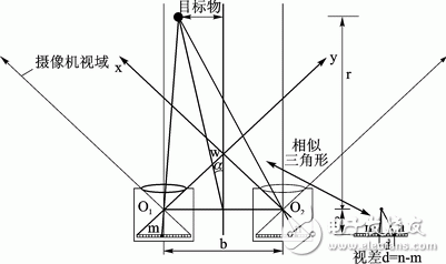
1 analysis of binocular vision ranging principleThe guide system is based on binocular vision ranging technology. The image is acquired by using the calibrated dual CCD structure. The image matching technology is used to find the relative position of the obstacle. Finally, it is transmitted to the human brain in the form of audio signal to guide the blindness. the goal of. The schematic diagram of measuring the distance and orientation of the object at the front end of the camera using the binocular vision system is shown in Fig. 1.

Figure 1 Schematic diagram of binocular vision system
In Figure 1, the binocular cameras are placed in parallel with the optical axis. The pitch is the base length b, the camera focal length is f, O1 and O2 are the focal points, r is the distance from the target to the plane of the two camera center points, and the plane xwy is The field of view that the dual cameras can scan together, that is, the range of binocular ranging in the plane. The image points of the target on the CCD plane of the two cameras appear at different positions, that is, corresponding to different pixels m and n, and the pixel difference, that is, the parallax is the difference d. If D is used to represent the size of a single pixel, the formula for calculating r can be derived using the principle of geometric optics:
Similarly, the vertical distance of the target to the center axis of the binocular camera is calculated from similar triangles:
It is easy to see that increasing the length of the baseline b can increase the parallax, which can reduce the influence of the parallax calculation error; however, the increase of the baseline also means the reduction of the viewing area and the difficulty of matching, so it is necessary to coordinate reasonably. The size of both.
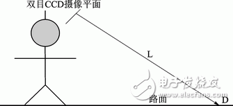
2 software and hardware designThe walking diagram of the blind person is shown in Figure 2.

Figure 2 Schematic diagram of blind walking
The binocular vision guide system is a real-time system that requires a combination of hardware and software. Due to the large amount of information that needs to be processed for image acquisition, in order to simplify the system, this design uses a linear array CCD to scan the oblique plane (this plane is a plane formed by the center point O of the imaging plane and the plane of the L and D ends of the busbar). Obstacle information. The blind person is flexible when walking. Wearing the guide blind system can better scan from the plane area to the space area, and achieve the purpose of guiding blindness.
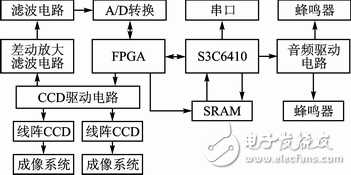
2.1 Hardware DesignThe block diagram of the hardware design is shown in Figure 3. The system uses the embedded controller ARM11 as the core of the S3C6410 chip to coordinate the work of various components, and the S3C6410 controls the FPGA to generate the strobe and read and write control signals of the peripheral devices. The obstacle is imaged on the CCD through the imaging system, and the generated image charge packets are sequentially output through the transfer pulse. Since the signal generated by the charge packet is weak and the output signal contains various noises, in order to facilitate the extraction of the useful signal for processing, it is necessary to improve the signal-to-noise ratio and suppress the noise.

Figure 3 hardware design block diagram
This design uses a differential amplification filter circuit to process the output signal of the CCD, and becomes a digital signal that can be processed by the S3C6410 through A/D conversion. In order to simultaneously extract two CCD signals for matching, two A/D converted gray scale data are sent to the FPGA, merged by the data selector, and then sent to the dual port SRAM buffer. Finally, the S3C6410 reads the two CCD signals in the dual-port SRAM for matching processing, and solves the obstacle depth information, which is converted into a voice signal prompt through the audio driving circuit.
Orange Circular Cable With SAA approval
Application: Those LV Power Cables suitable for power networks, direct burial, outdoors, indoors and in cable ducts, where not subject to mechanical damage may occur.
Standard applied: AS/NZS 5000.1Rated Voltage: 0.6/1kV
Certificates Approvals: SAA
Others: Fire Cable and other property Low Voltage Power Cable can be available
Orange Circular Cable,Circular Cable,Orange Circular Wires,Circular Wires
Shenzhen Bendakang Cables Holding Co., Ltd , https://www.bdkcables.com