Abstract: In the design of reactor control and protection system based on field programmable gate array (FPGA), anti-interference is applied to the electromagnetic interference of various electronic devices by using signal isolation, noise cancellation, descitation and threshold adjustment circuits in hardware design. Measures, and use software to improve anti-interference ability, achieve electromagnetic compatibility design, provide strong anti-electromagnetic interference capability for reactor control and protection system, and ensure safe, reliable and stable operation of the reactor.
1 IntroductionElectromagnetic compatibility refers to the ability of electronic equipment to suppress external electromagnetic interference. At the same time, the electromagnetic interference generated by the equipment should be lower than the specified limit and cannot affect the normal operation of other electronic equipment in the same electromagnetic environment. With the increasing popularity of electronic devices, electromagnetic interference has become increasingly serious, and the design of electromagnetic compatibility has become more important. Electromagnetic compatibility design is a complex system engineering. The design should refer to the actual electromagnetic environment to make specific requirements, and then propose technical solutions.
The reactor control and protection system involves a wide variety of electronic devices and complex internal circuits, including digital signal processing systems, input/output channels, digital display devices, interface circuits, drive circuits, control modules, and regulated power supplies. A combination of digital circuits coexisting, hardware and software. Electromagnetic interference of electronic equipment not only affects the functions of important reactor safety equipment and systems to varying degrees, but also may pose a threat to the safe operation of the reactor. In order to improve the reliability of the control and protection system, it is necessary to effectively suppress various electromagnetic interferences, optimize circuit design and software design, and ensure safe and reliable operation of the reactor. In this paper, the design and implementation method of electromagnetic compatibility is proposed for the field control gate array (FPGA) based reactor control and protection system to ensure the system has strong anti-interference ability.
2 Causes of electromagnetic interference 2.1 Grid interferenceThe reactor control and protection system adopts AC power supply, and the quality of the power grid directly affects the stability of the system operation. Grid interference includes surge voltage and electromagnetic interference. High-power electrical equipment at the system's job site can generate hundreds of volts, even thousands of volts of surge voltage with spark interference when starting or stopping.
2.2 Transmission line interferenceTransmission line interference is interference formed on the input and output lines. For the reactor system, there are more than ten kinds of analog signals transmitted from sensors and detectors. There are dozens of switch signals transmitted from the console and the control cabinet. The length of the transmission line is several tens of meters to hundreds of meters. This makes it easy to introduce interference from the job site into the system.
2.3 In-flight interferenceAny instrument that is working is itself a source of interference. Interference signals include spark discharge interference, self-oscillation, spike interference, and noise voltage generated by the relay.
3 Anti-jamming measures adopted in hardware design 3.1 Isolation technologyIn the design of control protection system, each instrument based on FPGA (including safety protection system, pulse stick control system, alarm system, calibration protection instrument, password authority unit) is FPGA-based programmable system-on-chip (SOPC). The embedded system receives the digital input signal from the console or from other instruments, as well as the analog and pulse signals transmitted from the sensor, and at the same time outputs important control signals to the relevant instrumentation or remote device as signals. source.
In order to prevent noise from being transmitted into the instrument along with the signal, each instrument uses a DC value stream power converter to isolate the power supply, and uses an optocoupler in the signal input and output channels to make the switching signal and the input/output signals of the FPGA. Isolation is immune to electromagnetic interference. Figure 1 shows the signal isolation circuit.
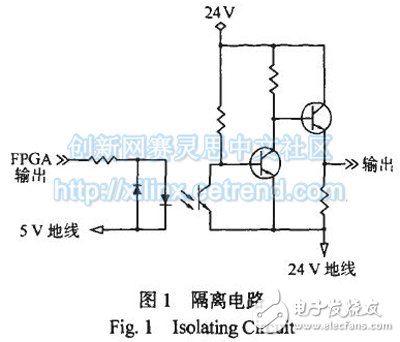
A 0.1 laF noise canceling capacitor is connected in parallel with the signal input to filter out high frequency noise.
In the circuit design, a large number of digital instrument control devices are used, and each digital meter control device itself is a pulse interference source, which will interfere with each other through the power line. The solution is to use a decoupling bypass method, that is, a 10 I_tF/35 V tantalum capacitor is connected in parallel with the power supply terminal of the printed circuit board for power supply decoupling, and a 0.1 in parallel at the power input end of each chip. High frequency, low distribution inductance ceramic capacitors for shrimp.
In order to improve the anti-jamming capability of the system, a complementary metal oxide semiconductor (CMOS) integrated circuit with the highest noise margin, a low-noise metal film resistor and a tantalum capacitor are selected in the circuit.
For operational amplifiers and AC/DC converters used in circuits, the higher the speed, the more susceptible they are to electromagnetic interference. Due to the low speed requirements during design, non-high speed op amps and AC/DC converters are used to reduce the effects of interference.
3.3 Self-excitation elimination3.3.1 Causes of Self-excitation For an amplifier circuit that introduces negative feedback, its input parasitic capacitance (including the input capacitance of the operational amplifier and the distribution capacitance of the wiring) and the feedback resistor will form a hysteresis network, causing the output voltage phase to lag. When the input signal frequency is high, the bypass action of the parasitic capacitance deteriorates the high frequency response of the amplifier, thereby affecting the stability of the circuit.
Kitchen Range Hood Motor,Range Hood Motor,Kitchen Range Hood,Range Hood Fan Motor
WUJIANG JINLONG ELECTRIC APPLIANCE CO., LTD , https://www.jinlongmotor.com