With the development of science and technology, cars are moving in the direction of intelligence. As the degree of intelligence of automobiles increases, sensors are increasingly used in automobiles. The position of the accelerator pedal is an important parameter in the intelligent control of automobiles. At present, the angular position sensors on the market are mostly expensive, bulky and have a low life. Therefore, it is particularly important to develop an accelerator pedal angle sensor that is low in price, small in size, and relatively long in life. The purpose of this design is to develop a non-contact angle sensor based on Cypress Semiconductor's programmable system-on-chip CY8C29466.
This article refers to the address: http://
Design principle
First, a three-point LC sine wave oscillation circuit is used to generate a sine wave signal. The inductance L in the circuit changes with the measured angle; then the sine wave signal is input to the voltage comparator to obtain a square wave signal; The wave signal is input to the single chip for processing, and according to the frequency of the square wave signal, the single chip outputs a voltage and frequency signal which are linearly related to the angle.
1. Three-point LC sine wave oscillation circuit
Figure 1 shows the basic three-point LC sine wave oscillation circuit. For a three-point LC sine wave oscillation circuit to work properly, it must have an oscillation circuit (at least two energy storage elements), an oscillating energy source (power supply + Vcc), and Control element (triode).
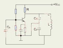
Figure 1 (a): Three-point LC sine wave oscillator circuit
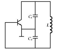
Figure 1 (b): Three-point LC sine wave oscillator circuit
2. Mixed signal PSoC
The traditional single-chip microcomputer only includes the digital logic system, and the CY8C29466 used in this design not only has a digital logic system, but also has an analog module and an analog-digital mixed-signal module, such as a gain programmable amplifier, a voltage comparator, an analog-to-digital conversion module, and an analog-to-digital conversion. Module. The chip's high integration features save the entire design and reduce the size of the components.
hardware design
The hardware part of the sensor mainly consists of two parts, of which CY8C29466 and peripheral circuits are the first part. CY8C29466 is mainly responsible for measuring the frequency of the signal, performing temperature correction and corresponding linearization processing, and outputting voltage signals and frequency signals.
The peripheral circuits mainly do the following work:
1. Voltage conversion, converting the 10V voltage supplied to the temperature sensor to 5V, as the power supply for the microcontroller and potentiometer;
2. Ambient temperature measurement;
3. Form an oscillating circuit;
4. Double circuit protection to improve product reliability. The function of the second part of the sensor is to change the inductance of the coil by changing the angle to change the angle.
The devices used in the hardware section are shown in Table 1.
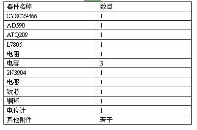
Table 1: Components used in the CY8C29466 design
software design
The modules used in the design process are: ADCINC12, CMPPRG, DAC8, INSAMP, PGA, PWM16_1, PWM16_2, Timer16, Counter24. Their position and connection to each other are shown in Figure 2. Among them, the analog-to-digital conversion module ADCINC12 is used to convert the analog signal collected by the temperature sensor into a digital signal for the correction of the sensor output; the voltage comparator module CMPPRG, the inverting amplifier module INSAMP and the gain programmable amplifier module PGA three modules Together with several external electronic components, a three-point sine wave oscillation circuit is formed; the digital-to-analog conversion module DAC8 is used to generate the voltage output signal of the sensor; the pulse width modulation module PWM16_1 is used for the clock source of the digital-to-analog conversion module DAC8, which improves the digital-to-analog conversion. Accuracy; pulse width modulation module PWM16_2 is used to generate the frequency output of the sensor; timer module Timer16 and counter module Counter24 are used to calculate the frequency of the input signal.
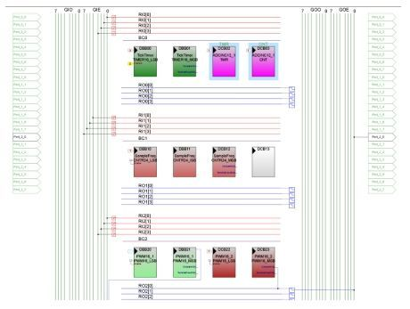
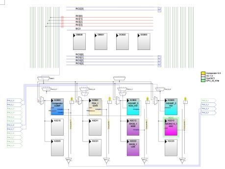
Figure 2: User Module Diagram
The execution process of the program is shown in Figure 3.
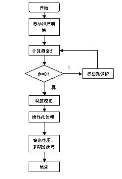
Figure 3: Program execution flow chart
Comparison of design schemes
Using PSoC has the following three advantages over traditional microcontrollers:
1. The number of components used is reduced. Since the PSoC contains an analog module that can output analog signals, many analog devices can be saved during the design process. Table 2 shows the devices used in the absence of the PWM signal output function when designing with a conventional single-chip microcomputer. This can be clearly seen by comparing Tables 1 and 2.
2. The cost is greatly reduced. The number of components used is reduced, and the market price of PSoC chips is generally lower than other conventional single-chip microcomputers, so the cost is reduced. A rough estimate of the cost can be reduced by 20% to 30%.
3. Shorten the design cycle. This is mainly manifested in two aspects: in terms of hardware design, due to the reduced number of components used, the circuit is simple, reducing the time spent on design; in terms of software design, efficient development tools provide users with efficient development tools, and traditional Compared to single-chip microcomputers, PSoC requires very little code, while traditional microcontrollers require users to write a lot of code.
Product features and application prospects
Compared with the existing similar products on the market, this product has the following characteristics:
1. Non-contact.
During the working process, there is no contact between the two parts of the relative movement, which eliminates the possibility of inaccurate measurement due to wear and prolongs the life of the product.
2. Temperature correction.
This product has temperature correction capability, and changes in ambient temperature within a certain range will not affect the accuracy of the measurement.
3. Linearization.
The two signals output by this product: voltage value, the frequency of the PWM wave is linear with the angle.
4. Two output signals.
This product has two output signals, users can choose one of the output signals according to their needs, or use two signals at the same time.
5. Dual loop protection.
This product has a dual-loop protection system. When one of the circuits fails, the other circuit will work immediately to ensure normal operation and improve product reliability.
6. Small size and low price.
The above characteristics determine that this product will have a good application prospect. It has high reliability, long life, accurate output measured in linear relationship, small volume, low price and fully meet the requirements of users, and is the first choice of the majority of automobile manufacturers. In addition to the angle measurement for the accelerator pedal of the car, the product can also be used for angle measurement in other applications, such as the precise control of electric bicycles.
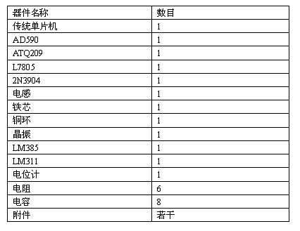
Table 2: Components used in traditional microcontroller design
The utility model relates to a medical atomization treatment and humidifying device belonging to the technical field of medical equipment and household appliances.
Professional Medical Atomization manufacturer is located in China, including Medical Vape,Dose Control Vape Pen,Supersonic Wave Vape, etc.
Medical Atomization,Medical Vape,Dose Control Vape Pen,Supersonic Wave Vape
Shenzhen MASON VAP Technology Co., Ltd. , https://www.masonvap.com