The equivalent circuit is also called "equivalent circuit". Under the same given conditions, it can replace another circuit with the same external performance. The electromagnetic process of electrical equipment such as motors and transformers can be analyzed and studied with their corresponding equivalent circuits.
The equivalent circuit is to reduce a complex circuit into a simple circuit with the same functions as the original circuit through methods such as resistance equivalent, capacitance equivalent, and power supply equivalent. This simple circuit is called the equivalent circuit of the original complex circuit.
Drawing steps of equivalent circuit diagram1. Carefully review the question, draw the original picture on the draft paper, and draw the state of the switch and the position of the sliding piece of the sliding rheostat according to the intention of the question;
2. According to the priority of the current path, use an eraser to erase the components that have no current passing through, and at the same time erase the disconnected switch and the components connected in series with it, and replace the closed switch with a wire;
3. Correctly analyze the connection method of the circuit, clarify which part of the circuit is measured by the ammeter, and whose voltage is measured by the voltmeter, and then organize the circuit diagram to draw the equivalent circuit diagram;
4. Mark the known conditions on the equivalent circuit diagram as much as possible;
5. Find out which equivalent diagram corresponds to the required physical quantity, and then according to the characteristics of the series and parallel circuits, pay special attention to the constant power supply voltage and the constant resistance value of the fixed-value resistor, and correctly use the electrical formula to analyze and answer.
Skills of equivalent circuit drawingThe first method is called end-to-end connection. If it is all connected end-to-end, it must be connected in series. If it is connected end-to-end, it must be connected in parallel. If it is both end-to-end and end-to-end, it must be a hybrid connection.
The second method is called the current flow method. According to the current flow, the characteristics of series and parallel connections are judged, and series, parallel and hybrid circuits are judged.
The third method is called the hand-to-hand method, which means that if one user is arbitrarily removed, the other electrical appliances must be connected in series; if one electrical appliance is arbitrarily removed, and other electrical appliances can work, it must be connected in parallel; For electrical appliances, other electrical appliances must work in hybrid connection.
The fourth method is called node method
1. Mark the equipotential point. Find each equipotential point in turn, and mark the letters of each equipotential point sequentially from the high potential point to the low potential point.
2. Draw sketches by kneading the equipotential points. That is, pull several equipotential points with the same electric potential together into one point, and then imagine that this point is "jittered" to straighten out the resistance of the same current direction from this point to the next node, and draw it point by point. sketch. When drawing a picture, pay attention to marking the current "several paths" at each equipotential point and the connection relationship with the next node.
3. Sort out the circuit diagram. It should be noted that the equipotential point and the serial number of the resistance correspond to the original diagram one-to-one, and the equivalent circuit diagram after sorting strives to be standardized for calculation.
Detailed explanation of eight ways of drawing equivalent circuit diagrams1. Telescopic wire method
If there is no electrical connection between two points on the wire, the wire between these two points can be extended or shortened, or even reduced to one point.
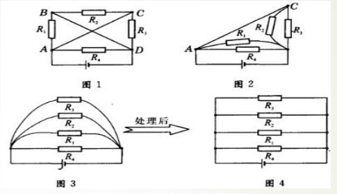
Example 1: Redraw the circuit of Figure 1 into a string. Equivalent circuit with obvious parallel relationship.
Analysis: Because there are no electrical appliances between points B and D. There are no electrical appliances between points A and C, so the BD and AC wires can be shortened: first shrink the wire BD to a point to get the circuit in Figure 2, and then shrink the wire AC to a point to get the circuit in Figure 3 , And finally the equivalent circuit can be obtained as shown in Figure 4.
2. Pull the wire method
Pull the connection points in the circuit up and down, left and right, and then process the equivalent circuit with obvious series and parallel relationships.
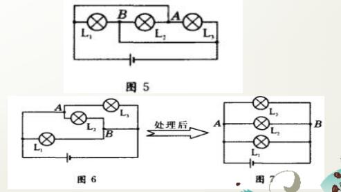
Example 2: Redraw the circuit of Figure 5 into a string. Equivalent circuit with obvious parallel relationship. Analyze, pull point A up and then to the left, pull point B down and then to the right to get the circuit in Figure 6; after processing, you can get the circuit in Figure 7 that is the problem.
No matter how long the wire is, as long as there is no power supply or electrical appliance connected in between, the two ends of the wire can be regarded as one point, so as to find the common point at both ends of each electrical appliance. This method can be used to identify irregular circuits.
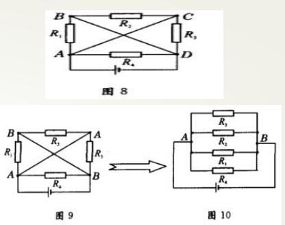
Example 3: Redraw the circuit in Figure 8 into an equivalent circuit with obvious serial and parallel relationships.
Analysis: Because there are no electrical appliances connected to the AC and BD wires, the AC and BD wires can be treated as two points A and B; then it can be seen that four resistors are connected in parallel between the two points A and B, and these four Connect two resistors in parallel between points A and B, making them the common point of the resistors to obtain the circuit shown in Figure 10.
4. Mobile node method
A node can be moved from one place on the wire to another, but it cannot go over the power supply and electrical appliances.
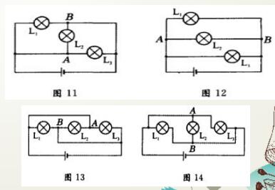
Example 4: Redraw the circuit in Figure 11 into an equivalent circuit with obvious serial and parallel relationships.
Analysis: Move node A to the left on the left wire, and move node B to the right on the right wire. The circuit in Figure 12 is what is required in the question.
Example 5: Redraw the circuit in Figure 13 into an equivalent circuit with obvious parallel relationship.
Analyze moving node A upwards and node B downwards, and the circuit in Figure 14 is what is required in the figure.
5. Component removal method
The dismantling method is an important method to identify more complicated circuits:
Once the electrical appliances on one section of the circuit are removed from the series circuit, the electrical appliances on the other sections cannot work normally.
Parallel circuit---After removing the electrical appliances on one of the branches, the electrical appliances on the other branches can still work normally.
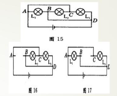
Example 6: Redraw the circuit of Figure 15 into an equivalent circuit with obvious serial and parallel relationships.
Analysis: The circuit of Figure 16 is obtained after L1 is removed: The circuit of Figure 17 is obtained after L2 is removed: The circuit of Figure 18 is obtained after L3 is removed: Analysis of the three diagrams shows that no matter which bulb is removed, the remaining bulbs can glow normally, so the three lights are connected in parallel. Then it is not difficult to draw the equivalent circuit diagram.
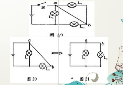
6. Simplified circuit method
The method of removing disconnected switches or short-circuited electrical appliances is called simplified circuit method.
Example 7: Redraw the circuit in Figure 19 into an equivalent circuit with obvious serial and parallel relationships.
Analysis: After removing S.L3 and simplifying, the circuit of Figure 20 is obtained, and the circuit of Figure 21 is obtained after pulling the wire.
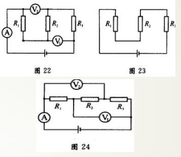
7, the ammeter supplement method
For the circuit with an electric meter, the electric meter supplement method can be used to analyze: the connection of the voltmeter for text content is regarded as an open circuit, and the connection of the ammeter as a wire. Because the resistance of the wires, switches, and ammeters is very small, the wires at both ends of the voltmeter can be moved in the circuit equivalently. During the movement, the wires at both ends of the voltmeter can cross any wires, switches, and ammeters in the circuit. Such as components with small resistance values, and hardly affect the reading of the voltmeter.
Example 8: Redraw the circuit of Figure 22 into an equivalent circuit with obvious series and parallel relationships.
Analysis: The voltmeter is regarded as an open circuit, and the ammeter is regarded as a wire. Remove the voltmeter and ammeter to obtain the circuit of Figure 23; straighten the wire, and then add the voltmeter and ammeter to obtain the circuit of Figure 24, which is what you want .
When measuring the voltage with a voltmeter, the voltage at both ends of the circuit is measured. However, in some circuits with a voltmeter, which part of the circuit is measured by the voltmeter, some students still do not understand, this problem can also be solved Use the method of drawing an equivalent circuit diagram to solve it.
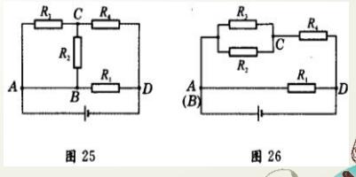
8. Current trend method
According to the current shunt direction and the sequence of electrical connections, the method of redrawing the circuit diagram is called the current direction method.
Example 9: Redraw the circuit in Figure 25 into an equivalent circuit with obvious serial and parallel relationships.
Analysis: The current flows from the positive pole of the power supply through point A and then divides into three paths (the AB wire can be reduced to one point), and flows through the external circuit for a week from point D to the negative pole of the power supply. The first road goes directly to point D through R; the second road goes to point C through R2, and the third road goes to point C through R. Obviously, R2 and R are in parallel between the two points AC; the second and third paths converge at Point C passes through R and reaches point D. It can be seen that Rz and R are connected in parallel with R, and then connected in parallel with R,. The circuit shown in Figure 26 is the result of the problem.
Pos Machine ,Card Swipe Machine,Credit Card Swipe Machine,Pos Terminal Machine
ShengXiaoBang(GZ) Material Union Technology Co.Ltd , http://www.sxbgz.com