0 Preface
The piezoelectric ceramic actuator (PZT) is the core of the micro-displacement platform. Its main principle is to use the inverse piezoelectric effect of the piezoelectric ceramic to generate deformation, thereby driving the actuator to undergo micro-displacement. Piezoelectric ceramic drivers have the advantages of high resolution, fast response frequency, large thrust and small volume, and have been widely used in aerospace, robotics, micro-electromechanical systems, precision machining and bioengineering. However, the application of piezoelectric ceramic drivers is inseparable from the piezoelectric ceramic driving power supply with good performance. To achieve nano-scale positioning applications, the output voltage of a piezoelectric ceramic drive power supply needs to be continuously adjustable within a certain range, and the voltage resolution needs to reach millivolts. Therefore, piezoelectric ceramic drive power technology has become a key technology in piezoelectric micro-displacement platforms.
1 Piezoelectric drive power system structure
1.1 Classification of Piezoelectric Drive Power
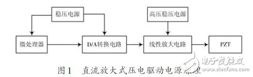
With the development of piezoelectric ceramic micro-displacement positioning technology, various driving power sources dedicated to piezoelectric ceramic micro-displacement mechanisms have emerged. At present, the form of the driving power source mainly includes a charge control type and a DC amplification type. The charge-controlled drive power supply has zero drift and the low frequency characteristics are limited by its application. The DC amplified driving power supply has the characteristics of good static performance, high integration and simple structure. Therefore, the design principle of this paper adopts DC-amplified piezoelectric driving power supply. The principle of DC amplified power supply is shown in Figure 1.
1.2 DC amplified piezoelectric drive power supply system structure
The driving power supply circuit is mainly composed of a microprocessor, a D/A conversion circuit, and a linear amplification circuit. The microprocessor controls the D/A to generate a high-precision, continuously adjustable DC voltage (0~10 V), and linearly amplifies and amplifies the DC voltage of the D/A output through an amplifying circuit to control the PZT-driven precision positioning platform.
In this design, LPC2131 is used as the microprocessor to generate control signals and waveforms. The 18-bit voltage output DA chip AD5781 is used as the main chip of the D/A conversion circuit to generate continuously adjustable DC low-voltage signals. The power of APEX is adopted. The amplifier PA78 acts as a power amplifier component and outputs a high voltage signal of 0 to 100 V to drive the PZT. To achieve high resolution piezo driver applications, the resolution of the piezoelectric driver power supply is designed to be on the order of 1 mV.
2 ARM-based low voltage circuit design
2.1 Introduction to ARM Controller
The ARM controller in the piezoelectric ceramic drive power supply mainly provides two functions: providing a universal input/output interface as a communication device; operating a related control algorithm as a controller and generating a control signal or waveform to implement a static positioning operation of the PZT. In response to the above requirements, the design uses the LPC2131 as the main controller. The LPC2131 is a 32-bit ARM7TDMI-S-CPU based microcontroller that supports real-time simulation and tracking. The main frequency can reach 60 MHz; the LPC2131 has 8 KB internal. On-chip static RAM and 32 KB embedded high-speed FLASH memory; has two general-purpose UART interfaces, an I2C interface, and an SPI interface. Because LPC2131 has high data processing capability and rich interface resources, it can be used as a control chip for piezoelectric driving power.
2.2 D / A circuit design
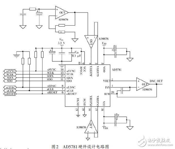
Since the piezoelectric drive power supply requires an output voltage range of 0 to 100 V and a resolution of millivolts, the resolution of the D/A needs to be sub-millivolt. This design uses the AD5781 as a D/A device. The AD5781 is an 18-bit, high-precision converter with an SPI interface that operates from -10 to 10 V and provides ±0.5 LSB INL, ±0.5 LSB DNL, ​​and 7.5 nV/Hz noise spectral density. In addition, the AD5781 features extremely low temperature drift (0.05 ppm/°C). Therefore, the D/A converter chip is particularly suitable for acquisition and control of precision analog data. The D/A circuit design is shown in Figure 2.
In the hardware circuit design, due to the precision architecture adopted by the AD5781, it is required to force detection to buffer its voltage reference input to ensure the specified linearity. Therefore, the amplifier chosen to buffer the reference input should have low noise, low temperature drift and low input bias current characteristics. Using the AD8676, the AD8676 is an ultra-precision, 36 V, 2.8 nV/Hz dual op amp with 0.6 μV/°C low offset drift and 2 nA input bias current, which provides a precision voltage reference for the AD5781. The C57 and LDAC pin levels of the AD5781 are pulled low through a pull-down resistor to set the AD5781 to the DAC binary register encoding format and the configuration output to be updated on the rising edge of SYNC.
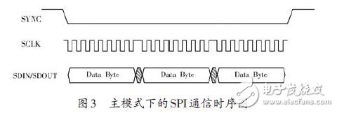
In the ARM software design, in addition to properly configuring the relevant registers of the AD5781, the clock phase, clock polarity, and communication mode of the SPI should be properly configured. The correct SPI interface timing configuration diagram is shown in Figure 3.
For Oil Immersed Power Transformer, we can produce voltage from 35kV to 500kV, capacity upto 460MVA. We use the best quality of raw material and advance design software to provide low noise, low losses, low partial discharge and high short-circuit impedance for power transformer.
Our power transformer are widely used in national grid, city grid, rural grid, power plant, industrial and mining enterprise, and petrochemical industry.
Cast Resin Transformer,Power Transformer,Renewable Transformer,Power Transformer With Oltc
Hangzhou Qiantang River Electric Group Co., Ltd.(QRE) , https://www.qretransformer.com