Large-scale systems should adopt a distributed network architecture, and should have openness and good scalability to adapt to changing application environments and requirements; each module in the system processes different types of data, and should have relative independence and autonomy. In addition, they are interrelated at different levels to achieve mutual access and collaborative work; the system should also have good integration, an effective component construction framework is required at the functional level, and a unified data interaction platform at the component level.
Based on the above analysis, we choose CPCI bus as the data communication platform of the distributed system. CPCI bus technology is a combination of PCI bus technology and mature European card assembly technology. In terms of electrical, logic and software functions, it is fully compatible with the PCI standard, and it breaks through the PCI standard's four slots limit. Compared with the VME bus The module is low in price, has the advantages of openness, easy expansion, high density, etc., while achieving high availability of 99.999%. Using CPCI bus technology and hardware interface design specifications, it can use its multi-module plug-in card design advantages to support distributed processing of multiple services, and realize the seamless connection of modular data processing units to provide high-speed, high-speed, Reliable guarantee, very suitable as a distributed system business processing communication platform, and also suitable for a wide range of applications in communication and embedded systems.
This paper presents a communication system design based on the CPCI bus. The system uses a distributed network architecture to support the processing and data interaction of multiple packet switching services. The article first gives the system structure and principle design, and aims at the difficulty of cross-bus communication of distributed business processing modules, proposes a message storage and address information maintenance strategy based on the "drawer mechanism", and describes the realization of key technologies such as interference-free data transmission. , And finally give a technical summary and outlook.
2. System overall design 2.1 System structure characteristicsThe distributed system structure we designed is shown in Figure 1. Different equipment boards in the system independently process the corresponding business data, convert it into unified IP data for intercommunication, and maintain their own routing tables to independently complete data forwarding. The system distributes the interface with a specific business network to various equipment boards for standard access channel adaptation, and distributes various network data to each board for processing and forwarding, realizing centralized configuration and distributed access Perfect combination with data processing.
In the CPCI distributed bus architecture, the backplane provides physical connections and circuit guarantees for bus switching, and the system slots on the backplane provide functions such as bus arbitration, clock distribution, and restart of the boards on the backplane; peripheral slots can be placed Simple interface board, intelligent slave device or bus control device. Each CPCI board has a processor and an embedded real-time system. The processor uses Motorola's PowerPC-860, and at the same time uses PLX's 9054 and 9056 PCI bridge chips to set up an efficient and stable transmission between the PowerPC-860 and the CPCI bus. bridge. PLX 9054/9056 chip realizes the function of CPCI master control device, supports PCI2.2 regulations, simplifies the design of connecting to PowerPC, has good compatibility, and can be easily expanded into 66MHz clock and 64bit PCI bus, especially in PLX 9056 Embedded bus arbiter can reduce the system scale and make the system more stable.
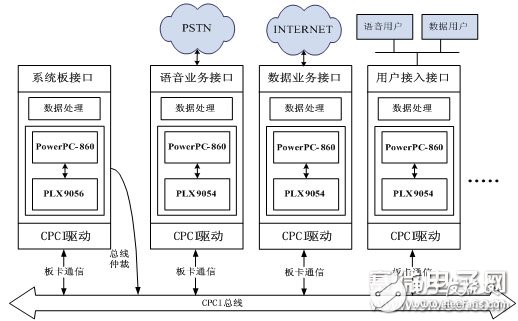
Figure 1 Data communication system structure diagram
2.2 System resource sharing and information exchangeThe system adopts a CPCI-based single-bus multi-processor/multi-operating system distributed architecture. Each board in the system has independent CPU and operating system, address and memory space, and independent I/O and interrupts, which can be completed independently For data operation, each board can be regarded as a computer host. The topological structure formed by the distributed system is a fully connected network, and each node in the network can directly access other nodes; from the perspective of CPCI bus transmission, the boards on all slots are equal and can act as The master actively initiates a bus transfer. For this kind of bus-based distributed architecture, we designed a cross-bus memory access mechanism to map the system memory or device memory of other boards in the system or device memory (such as memory expansion cards) to the local address space, and then use it as the same as the system memory. Access the mapped memory in a way, so that each board can access the memory resources of other boards on the bus.
2.3 Unified standardized access interfaceHeterogeneous networks are connected to the distributed system through standard channel adaptation. Non-IP data such as voice, X.25 and serial data are converted into IP data through the data adaptation module. The embedded real-time system of each board in the system processes the data And interact. Various heterogeneous networks are connected to the corresponding network devices in the embedded system, and the network device driver calls the unified interface provided by the CPCI bus driver to realize the data transmission between the real-time system and the bus. When sending data, the network device driver uses the bus driver to control the bridge chip to perform address conversion, data forwarding, interrupt generation, etc., and generate the corresponding bus operation to send the data to the bus; when receiving data, the bus driver responds to the interrupt and receives the corresponding address on the bus Segment data, perform operations such as data analysis, address conversion, data forwarding, and other interrupt generation in the interrupt service program. We use the Linux operating system, and its network system is mainly based on the UNIX socket mechanism, and the system protocol stack and the driver transfer data through a special data structure (sk_buff). The data transmission process between the real-time system kernel and the CPCI bus is shown in Figure 2:
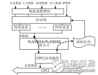
Figure 2 Data transmission flow chart
3. Key technology 3.1 "Drawer mechanism" for message storageEach board in the system shares a CPCI bus. We propose a message storage strategy based on the "drawer mechanism" to ensure interference-free transmission of data between boards. In the initialization phase when the board is added to the system, the system board allocates an independent PCI bus address interval for each board on the bus, and other boards write data to the designated address area when sending data to it. One board will receive data from different boards. In order to avoid interference caused by each board sending data to the same base address, the same board address area is allocated to other boards with the same independent read and write space. We will It is named "Drawer". In this way, the data from a certain board will be sent to its corresponding "drawer", and the data will be stored in order instead of being overwritten each time to ensure the processing time of the board. When the data length exceeds the remaining space of the drawer, it is like a ring buffer to store from the beginning. The "drawer mechanism" is shown in Figure 3. The squares on the left represent different boards on the bus, and the right is the PCI bus address space. The corresponding address range of board B is from point a to point e. The space between points ab is only used for data transfer from board A to B, and the space between points bc is only used for data transfer from board C to B. analogy.
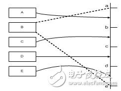
Figure 3 "Drawer" of board card data receiving
Based on this message storage mechanism, we define several address tables to maintain address information related to data transmission. A static base address table is maintained on the system board, which records the pre-allocated base address of the board on each card slot. All boards maintain a board address mapping table and a transmission address offset table. The board address mapping table is a structure array, each item in the array represents a card slot, which contains address information such as the board name, slot number, base address, and address range for configuration during data transmission. The data structure is as follows :
typedef struct _BUS_ADDR_MAPPING_INFO{
char board_nameï¼»BOARD_NAME_LENGTHï¼½;
int slot_number;
unsigned long base_addr;
unsigned long range;
ï½BUS_AddrMapping_Info, *P_BUS_AddrMapping_Info;
The transmission address offset table is an unsigned integer array, which is used to record the address offset of each board during data transmission between boards. The initial value is zero. Each time the transmission is completed, the address offset of the receiving board increases. When the length of the secondary data transfer, when the address space is not enough to store the data to be transferred, set the offset address to zero, and rewrite from the beginning of the area. The data structure is defined as follows:
u32 current_offset_tableï¼»NUM_OF_SLOTï¼½ = {0, 0, 0, 0, 0, 0, 0, 0};
3.2 Data transmission realizationWe define a data structure IPH (Internal Packet Header), which contains attributes such as data type, length, source card slot number, etc., before transmitting data as a packet header to encapsulate the message, so that the receiver can analyze the packet header according to the data service type Differentiate treatment. The main IPH types include board configuration information, port registration information, routing information, unknown data types, etc. Define the data structure iph_attr to distinguish different IPH_info types, located at the beginning of the data packet, and its data structure is as follows:
typedef struct _IPH_ATTR ï½›
u32 board_id; /*from which board*/
int iph_type; /*datagram type*/
unsigned long length; /*datagram length(without IPH)*/
ï½IPH_ATTR, *P_IPH_ATTR;
Different data structures are defined for various types of IPH information, which are sequentially stored after the iph_attr structure in the data packet header.
When sending data, IPH encapsulates the data, selects the destination PCI address according to the aforementioned board address mapping table, and then calls the bus interface function to complete the data transmission. The sender informs the receiver of the transmission address and data length information by writing the mailbox register of the receiving board bridge chip, and generates an interrupt to trigger the reception. The PLX bridge chip supports direct access from the local bus to the PCI bus. It has 8 mailbox registers. The first four can generate interrupts. Each mailbox is 32 bits. The transmission address and data length information use mailbox i and mailbox i+4 to work together. In this way, when the receiver receives two parameters, it will generate an interrupt to receive data [5]. This mechanism makes the receiving process have four service windows, which improves the system throughput.
The mailbox of the receiving board's PLX chip is written into the parameters and a local interrupt is generated to check the "drawer". Before the interrupt is generated, the data has actually been sent to the target board. The interrupt service program maintains a data queue for the receiving end. It reads the information in the mailbox, analyzes the address, finds the corresponding data, and sends it to the bottom half for processing. The IPH of the bottom half analyzes the data packet to distinguish the data type. If it is information such as configuration, port, routing, etc., it is configured accordingly, and if it is data information, it is processed or forwarded.
In summary, the system has completed the mapping of the PCI address space between the boards through the "drawer mechanism" and the maintenance of several address tables. The board can write data to the mapped address space and then transfer the data to the target through the bus. On the board, the board's cross-bus memory access is realized; the custom IPH data packet header is used to distinguish the data type to assist in data information management, complete the routing maintenance, the logic function of the forwarding engine, and realize the non-interference transmission of data and effective communication management .
4. Summary and OutlookThe author of this article has the following innovations: a distributed system design based on CPCI is presented, and a message storage mechanism and address information maintenance strategy based on the "drawer mechanism" are also proposed. The CPCI-based distributed system described in the article can reach a 64bit bus width and a peak bandwidth of 264MB/s. Each host in the system can independently complete data processing and communication, and can carry multiple services of voice and data. Users can also pass users The PSTN network connected to the access board and the voice service board and the Internet connected to the data service board carry out data communication, which has great application prospects in communication, military and other fields. In order to make this communication system more large-scale practical value, future work includes:
(1) Realize a set of easy-to-operate remote management system to complete the monitoring and deployment of communication services;
(2) Design CPCI interface boards that support more business types, such as xDSL, H.264, etc.;
(3) In the case of large external interference, pass strict performance tests to prove that the system can meet the telecom-level business requirements.
Product categories of Vozol, we are specialized electronic cigarette manufacturers from China, Vapes For Smoking, Vape Pen Kits, Vape Cartridge, Smoking Accessories,E-Cigarette suppliers/factory, wholesale high-quality products of Modern E-Cigarette R & D and manufacturing, we have the perfect
after-sales service and technical support. Look forward to your cooperation!
vozol disposable vape,puff bar vozol vape,vozol bar disposable vape kit,pod vozol bar vape,vozol vape pen
Ningbo Autrends International Trade Co.,Ltd. , https://www.mosvape.com