Texas Instruments DLP technology is a microelectromechanical system (MEMS) technology that uses digital micromirror devices (DMDs) to modulate light. Each of the DMD's micromirrors represents a pixel on the screen and is independently tuned to keep pace with the color sequence illumination for an amazing display. DLP technology supports the display of many products worldwide, from digital cinema projectors to smartphones. In 2014, a new DLP Pico chipset based on breakthrough micromirror technology was introduced. This micromirror technology is called DLP TRP (see Figure 1).
Texas Instruments' DLP TRP chipset has a pixel pitch of only 5.4μm, a deflection angle of 17 degrees, higher resolution, lower power consumption, and enhanced image processing while maintaining the best optical efficiency of DLP technology (Figure 1). The Texas Instruments TRP chipset is ideal for any display system that requires high resolution and high brightness at low power in a compact size.
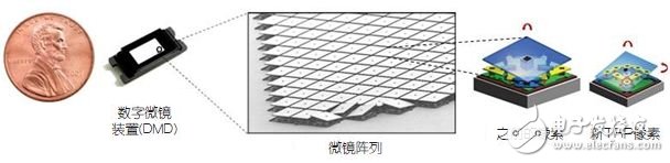
Figure 1: Texas Instruments DLP TRP technology: smaller, brighter, and lower power.
What is a near-eye display?
Near-Eye Display (NED), also known as a head-mounted display (HMD) or wearable display, creates a virtual image within the field of view of one eye or two eyes. From a human perspective, the virtual image appears to be outside of a distance, larger than the relatively small display panels and optics used to create the image. To better understand the experience provided by near-eye displays, let's look at another medium: audio (Figure 2).
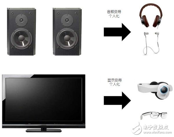
Figure 2: The evolution of media from large and shared to portable and personal.
Traditional speakers are large, inconvenient to carry, and create a shared listening experience. The earphones and earbuds are small and easy to carry, creating a personalized listening experience. Similarly, TVs and monitors are large and inconvenient to carry, creating a shared visual experience. The near-eye display is equivalent to the display area of ​​the headset, creating a compact, portable, personalized viewing experience.
What is a near-eye display?
Near-Eye Display (NED), also known as a head-mounted display (HMD) or wearable display, creates a virtual image within the field of view of one eye or two eyes. From a human perspective, the virtual image appears to be outside of a distance, larger than the relatively small display panels and optics used to create the image.
Near-eye display has several key advantages over traditional displays:
â— Small size, light weight and easy to carry;
â— Very low power consumption;
â— Can be seen through.
Large-screen TVs are large, but near-eye displays produce virtual images that look similar to large-screen TVs in small, wearable-sized packages.
Near-eye displays can be broadly classified into two broad categories: immersive and perspective (see Figure 3):
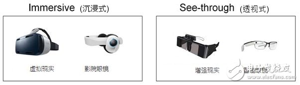
Figure 3: Two major categories of near-eye displays.
â— The immersive near-eye display blocks the user's real-world view and creates a large field of view image. Typically, the cinema glasses are 30 degrees to 60 degrees, and the virtual reality display is 90 degrees or more. These products can be used as a user's personal theater or gaming environment.
â— The see-through near-eye display keeps the user's real-world field of view open, creating transparent images or very small opaque images, blocking only a small portion of the user's peripheral vision. Perspective categories can be divided into two applications: augmented reality and smart glasses. The augmented reality near-eye display typically has an angle of view of 20 to 60 degrees, covering information and graphics over the user's real world field of view. The field of view of smart glasses (such as Google Glass) is usually smaller, and users will look at the watch regularly instead of continuously browsing the display.
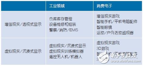
Near-eye displays can be used in a variety of applications in the industrial control and consumer electronics markets (Table 1).
Table 1: Near-eye displays can be used in a variety of applications in the industrial control and consumer electronics markets.
Optical elements of near-eye display systems using DLP technology
DLP technology is compatible with a variety of near-eye display optical systems (Figure 4). In general, optical systems using DLP technology must include:
• An illumination system – containing a light source (usually an RGB LED) and illumination optics that directs light onto the DMD;
â— DMD - intelligently reflects incident light to create an image;
• An optical system—collects the light reflected from the DMD and directs it into the human eye.
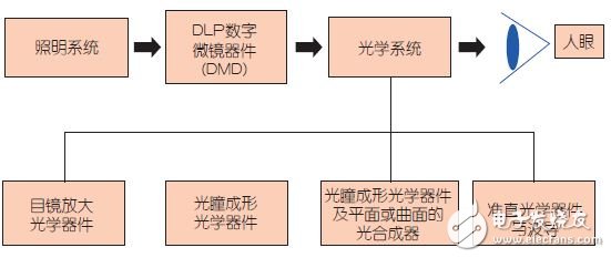
Figure 4: Overview of the optical system.
A common misconception about near-eye display optics is that the display is produced by an image of a small projection module placed on a translucent surface, such as a spectacle lens. This is not feasible because the eye cannot focus on objects that are close to it. In fact, the near-eye display optical system is very different from the traditional projection system—the near-eye display does not create a real image on a certain surface, but forms a pupil, which is the last component in the optical link and will be on the retina. Light from the pupil is converted into an image.
Waveguide-based designs (Figure 5) are particularly interesting because they have a transparent display and diaphragm expansion. The waveguide collects light at the input and then transmits the light to the human eye. It allows the microdisplay, optical system, and illumination to be placed outside of the human eye, such as on one side of the head, leaving only relatively small, lightweight, transparent waveguide optics in front of the human eye.
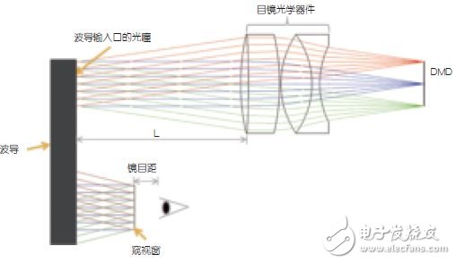
Figure 5: Basic waveguide optics using DLP technology (illumination optics not shown).
Optical design trade-off
The optical design of the near-eye display system requires multiple trade-offs. The four key parameters are field of view, resolution, contrast, and system size.
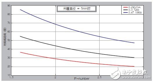
There are three main factors controlling the angle of view: 1. DMD size; The aperture value of the optical system; 3. The size of the pupil at the input of the waveguide. Figure 6 shows the comparison of the aperture value and the diagonal field of view for various DMD sizes for a pupil diameter of 5 mm. Key parameters include:
â— DMD size - field of view and resolution requirements are the driving factors for DMD diagonal size requirements. The larger the field of view, the larger the DMD required, and the larger the system size due to the larger optical system. Although the size of the DLP optical module varies by system requirements, it can be reduced to a few cubic centimeters in size, including LEDs, DMDs, illumination optics, and pupil forming optics.
◠Aperture value of optical design—The aperture value of the optical system represents the ratio of the focal length of the lens to the diameter of the entrance pupil. Typically, systems with lower aperture values ​​support larger field of view and greater optical expansion. However, the price is to increase the size of the optical system. In addition, a decrease in the aperture value results in a decrease in contrast. On the other hand, systems with larger aperture values ​​can produce higher contrast, reduce optical design complexity, and reduce optics size at the expense of field of view and etendue/brightness.
â— The size of the aperture of the waveguide input port - usually, if the waveguide is used to enlarge the aperture and increase the size of the eye box, a 5 mm aperture diameter is sufficient. For the same DMD diagonal, the larger the aperture, the smaller the field of view (Figure 7).
![]()
Figure 6: Relationship between aperture and field of view for various DMD sizes.
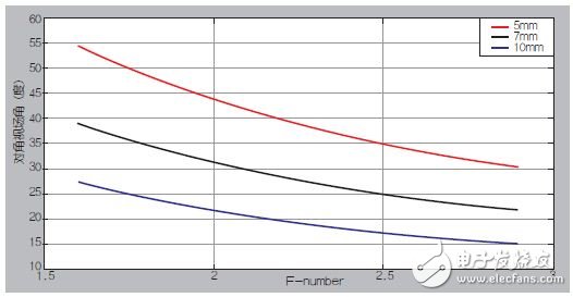
Figure 7: Relationship between aperture and field of view for various pupil sizes.
How the direction of illumination affects the optical layout and size
The DLP TRP architecture of the 5.4μm pixel DMD supports two possible illumination directions: side or bottom (Figure 8). These two options offer greater optical layout flexibility, such as a longer but thinner layout with side illumination and a shorter but thicker layout with bottom illumination, as shown in Figure 9. A variety of optical layouts are available, such as box, thin or L-shaped, depending on system requirements. For example, a thin, long optical module may be suitable for a waveguide-based design where the module is on the side of the head; and a short, thick optical design may be suitable to reduce the overall volume of the module.
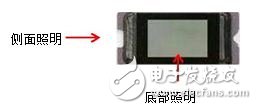
Figure 8: Flexible lighting direction - side or bottom
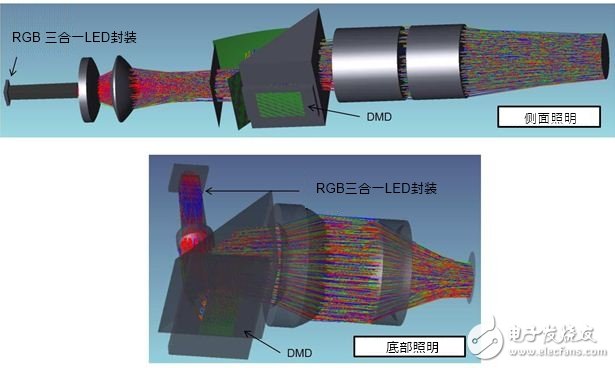
Figure 9: Example of optical design for side and bottom illumination directions
Precautions for system and electronic circuits for near-eye displays using DLP technology
The DLP Pico chipset is equipped with a small, efficient controller and a PMIC/LED driver that supports an integrated, reliable system with small size and low power consumption. The controller is only 7mm & TImes; 7mm, PMIC is only 3.4mm & TImes; 3.2mm (see Figure 10, board layout example). Typical power consumption of DMD and controller combination is 150mW~300mW, depending on array size and resolution. Figure 11 shows a typical system block diagram of a near-eye display application using a DLP technology solution.
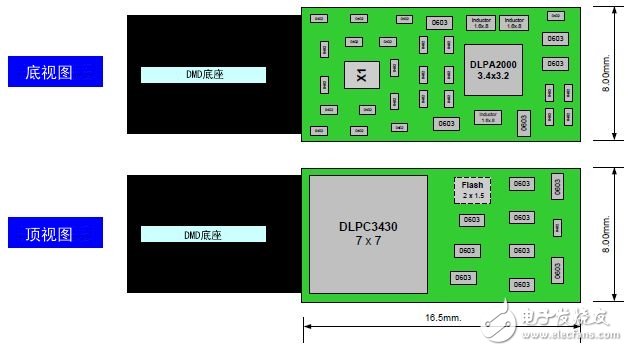
Figure 10: Example of a small board design
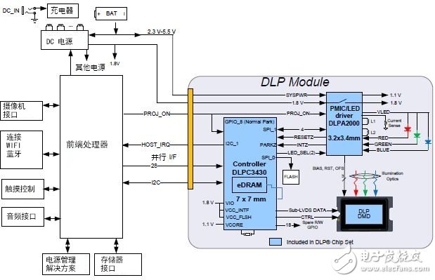
Figure 11: Example of a system block diagram
The DLP controller communicates with the front-end processor through the I2C and receives 24-bit RGB video data through the parallel interface. The front-end processor uses the PROJ_ON signal to control the power-up and power-down of the DLP system. The PMIC/LED driver provides all the necessary power for the controller and DMD, while the integrated LED driver provides configurable RGB LED current.
The chipset in Table 2 is ideal for near-eye display applications.
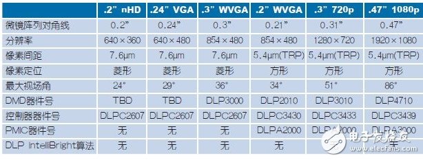
Table 2, chipset for near-eye display
Maximum field of view: (1) Ideal optical design assumed to be 5 mm pupil diameter with TRP of F/1.7 and VSP DMD of F/2.5
Why choose DLP technology for near-eye displays?
The use of DLP technology for near-eye displays has several key advantages:
â— High optical efficiency - DLP technology provides very high optical efficiency. The miniature aluminum micromirror reflects most of the incident light and creates a brighter near-eye display with lower illumination power.
â— Independent of polarization - DLP technology can be used with any light source including LEDs, lasers, laser phosphors and bulbs. If a non-polarized light source such as an LED is used, the optical system produced by the DLP-based solution is highly efficient because it does not require polarization conversion to compensate for losses.
The advantages of optical efficiency make DLP technology especially suitable for higher brightness near-eye display applications such as see-through and larger field of view applications. As the brightness increases, the power consumption advantage of the DLP system is also more pronounced (Figure 12).
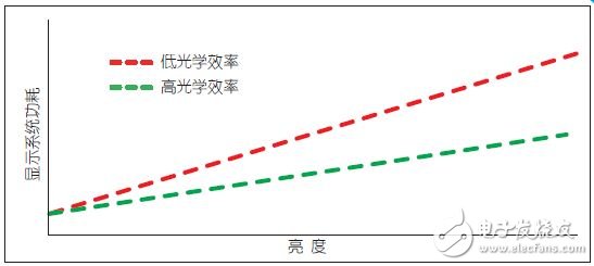
Figure 12: As the brightness increases, the power consumption of the optically efficient system decreases.
◠High Contrast—DLP technology supports contrast ratios over 2000:1 in optimal optical design, providing deep black for immersive displays and a highly transparent background for augmented reality displays (see Figure 13).
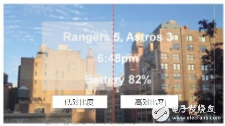
Figure 13: Low contrast (left) and high contrast (right)
â— High speed - low latency: DLP technology is one of the fastest display technologies in the world, and each micromirror can be flipped thousands of times per second. Therefore, the color refresh rate is fast and the delay is low, which is especially important for near-eye display applications.
In addition, Texas Instruments' TRP chipset has additional features that make it ideal for near-eye display applications.
â— Higher resolution and smaller size - TRP size is approximately 50% smaller than previous generation DLP pixel technology, and the same array size can achieve 2x pixels. For example, a 0.3" diagonal with TRP can support 1280&TImes; 720 pixels, while a 0.3" array diagonal with previous generation pixel technology only supports 854 & TImes; 480 pixels.
â— Flexible lighting direction - TRP can support side lighting and bottom lighting solutions for flexible optical design.
â— Low power consumption - The TRP chipset emphasizes energy savings during design. For example, the TRP 0.2 "WVGA (854 x 480) chipset consumes approximately 50% less power than the previous generation WVGA chipset, and the 0.3" 720p chipset consumes approximately 80% less power than the previous generation 720p chipset.
â— Advanced image processing algorithms - DLP The IntelliBright algorithm suite performs two important functions: 1. Content adaptive lighting control - dynamically adjusts each RGB LED to optimize power based on the content of each frame; 2. Local area brightness enhancement - Intelligently enhances darker areas of the image depending on ambient lighting conditions.
DLP technology is one of the most mature display technologies on the market. Texas Instruments has sold millions of DLP chips, and DLP Cinema is the technology of choice for nearly 90% of the world's digital cinema screens. The DLP chipset for near-eye displays uses the same core technology and converts it into a microdisplay that creates cinema-quality image quality in virtually any near-eye display application.
Marine High Temperature Pressure Sensor
Product overview high temperature pressure sensor is a signal measuring element. The measured medium pressure is transmitted to the sensor through the heat dissipation structure on the transmitter. The high-precision signal processing circuit is located in the stainless steel shell to convert the sensor output signal into standard output signal. The whole product has undergone strict testing and aging screening of components, semi-finished products and finished products, with stable and reliable performance, so that the product can work stably for a long time when used for pressure measurement of high-temperature medium. Product features 1. 316L stainless steel isolation diaphragm structure 2. Imported high temperature resistant chip 3. Wide applicable medium temperature range 4. Strong anti-interference and good long-term stability 5. Direct contact with high-temperature medium to improve pressure response frequency 6. Provide rich pressure range of low pressure, medium pressure and high pressure
Marine High Temperature Pressure Sensor,Marine Temperature Pressure Sensor,Pressure Sensor With Led Display,High Temperature Pressure Sensor
Taizhou Jiabo Instrument Technology Co., Ltd. , https://www.taizhoujbcbyq.com