In the industrial measurement and control system, 51 single-chip microcomputer is used to collect analog quantity and switch quantity in the field, and the central control computer is used to monitor the entire control site in the control room or dispatching room. Data transfer between them can form local networks, multi-user systems, and distributed control systems.
First, 51 single-chip computer and computer communication
A block diagram of remote bidirectional communication using a 51-chip serial interface and modem and an existing telephone line is shown in Figure 1-18.
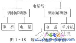
In serial communication using the existing telephone line for data transmission, the data to be transmitted is transmitted bit by bit on the common channel in order.
Serial communication has specific provisions for character encoding, character format, and transmission rate, and must be strictly observed. The transfer format of asynchronous serial communication data consists of four parts: start bit, data bit, parity bit and stop bit.
Communication protocol requirements: At the transmitting end, each character must be transmitted with a start bit, a data bit, a parity bit, and a stop bit string; at the receiving end, the start bit, data bit, and parity are also used. The check digit and the string of a stop bit are counted and received.
Brief introduction of 51 single chip serial interface
Among the 51 MCU pins, P3.0 (10-pin) is RxD (serial input port), and P3.1 (11-pin) is TxD (serial output port).
The 51 MCU serial interface is full duplex, ie it can transmit and receive simultaneously. The two serial port registers are accessed through the special function register SBUF, which is written to the SBUF load transfer register, and the read SBUF accesses the physically separate receive registers. The two buffers share an address 99H.
There are 4 working modes for the 51 MCU serial interface. Communication only uses modes 1, 2, and 3; mode 0 is mainly used to expand the parallel input/output port.
â— Mode 0 In the mode 0 state, the serial port is the synchronous shift register mode. Its baud rate is fixed and is osc/12. The data is input from the RxD terminal, and the synchronous shift pulse is outputted by the TxD terminal. The 8-bit data is transmitted and received, and the low bit is first.
â— Mode 1 In mode 1, the serial port is an 8-bit asynchronous communication interface, and one frame of information is 10 bits: 1 bit start bit (0), 8 data bits (low bit first), and 1 stop bit ( 1), the baud rate is variable.
â— Mode 2 and 3 Serial port is a 9-bit asynchronous communication interface in mode 2 and 3. The transmission and reception of one frame of information consists of 11 bits, 1 programmable data bit (9th data bit) and 1 bit stop. Bit (1).
The baud rate of mode 2 is fixed to osc/64/2SMOD, which is fosc/32 or osc/64. Mode 3 has a variable baud rate.
2, 51 single-chip serial interface level conversion
The standard specification of RS-232C is: logic 0 is +5~+15 V, logic 1 is -5~-15 V, and the serial port level of 51 MCU is TTL level. Therefore, level conversion is required to comply with the serial communication standard.
The level shifting uses the MC1488 and MC1489. Figure 1-19 shows its pin diagram. The MC1488 input level is TTL level and the output level is RS - 232C level. The MC1489 input level is RS-232C level and the output level is TTL level. In addition to level shifting, the above two dedicated chips implement positive and negative logic level conversion.
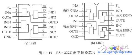
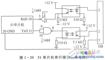
Figure 1-20 shows the actual conversion circuit connection diagram of the 51 MCU serial port. Considering the on-site interference factors, in order to suppress spikes and various noise interferences, two TIL117 optocouplers are added to the serial port circuit to enhance the reliability of data transmission.
Bluetooth Mini Projector
Sound can be transmitted wirelessly, no audio source cable is required.
1. The Bluetooth function of the projector can be connected to a Bluetooth speaker, and you can enjoy better sound quality when watching movies and playing music;2. After the projector is connected to the mobile phone through the Bluetooth function, the projector acts as a speaker and can play music from the mobile phone.
wifi bluetooth projector,bluetooth home projector,bluetooth protable home projector
Shenzhen Happybate Trading Co.,LTD , https://www.happybateprojector.com