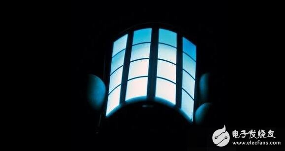
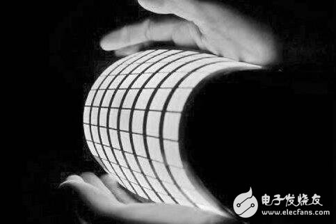
Organic Light-EmitTIng Diode (UIV OLED) is also known as Organic Electroluminescence Display (UIV OLED). It is a different type of illumination principle than liquid crystal display (LCD). OLED was discovered by the Chinese-American professor Ching W. Tang in the laboratory in 1979, and the research on OLED was carried out. OLED display technology has the advantages of self-illumination, wide viewing angle, almost infinite contrast, low power consumption, and extremely high reaction speed. However, the price (large display panel), life, and resolution cannot match the LCD monitor.
Organic light-emitting diodes can be classified into monochrome, colorful and full-color according to color. Among them, the preparation of full-color organic light-emitting diodes is the most difficult; according to the driving method, passive (Passive Matrix, PMOLED) and active (AcTIve Matrix, AMOLED) can be classified. ).
Principle of oled
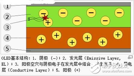
OLED refers to the phenomenon of light emission caused by carrier injection and recombination driven by an electric field. The principle is to use ITO glass transparent electrode and metal electrode as the anode and cathode of the device respectively. Under a certain voltage, electrons and holes are injected from the cathode and the anode to the electron and hole transport layer, respectively, and then migrate to the light-emitting layer respectively. The encounter forms excitons to excite the luminescent molecules, which emit radiation after being irradiated. Radiation light can be observed from the ITO side, and the metal electrode film also acts as a reflective layer.
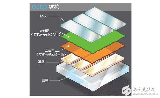
Oled structure
Base layer (transparent plastic, glass, metal foil) - the base layer is used to support the entire OLED.
Anode (transparent) - The anode eliminates electrons (increasing electron "holes") as current flows through the device.
Organic layer - The organic layer is composed of organic molecules or organic polymers.
Conductive layer - This layer consists of organic plastic molecules that carry "holes" from the anode. Polyaniline can be used as the conductive polymer of the OLED.
Emissive layer - This layer consists of organic plastic molecules (different from the conductive layer) that transport electrons from the cathode; the luminescence process takes place at this layer. Polyfluorene can be used as the emissive layer polymer.
The cathode (which may be transparent or opaque, depending on the type of OLED) - the cathode will inject electrons into the circuit when current is flowing through the device.
Oled's illuminating process and principle
OLEDs emit light in a similar way to LEDs, with a process called electrophosphorescence.
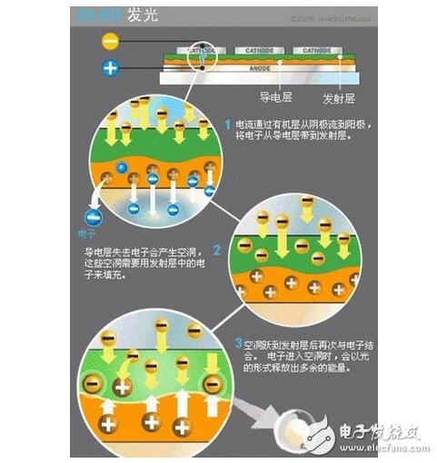
The specific process of OLED illumination is as follows:
1. The battery or power supply of the OLED device will apply a voltage across the OLED.
2. Current flows from the cathode to the anode and through the organic layer (current refers to the flow of electrons).
3. The cathode outputs electrons to the organic molecular emission layer.
4. The anode absorbs electrons from the organic molecular conduction layer. (This can be seen as the anode outputs holes to the conductive layer, and the effects are equal.
5. At the junction of the emissive layer and the conductive layer, electrons will combine with the holes.
6. When an electron encounters a hole, it fills a hole (it will fall into an energy level in the atom of the missing electron).
7. When this process occurs, electrons release energy in the form of photons.
8, OLED lighting.
9. The color of the light depends on the type of organic molecules in the emissive layer. The manufacturer will place several organic films on the same OLED to form a color display.
10. The brightness or intensity of light depends on the amount of current applied. The higher the current, the higher the brightness of the light.
OLED technology can be divided into two main types of small molecules and polymers, and their structures are not the same. However, whether it is a small molecule OLED or a polymer OLED, there is an organic light-emitting material layer between the thin and transparent conductive indium tin oxide (ITO film) cathode and the metal anode - this is similar to a hamburger. Sandwich cake-like structure. This structural layer includes a hole transport layer (HTL), a light-emitting layer (EL), and an electron transport layer (ETL).
Among them, the structure of the yin and yang poles is a standard crystal diode structure, which has unidirectional conductivity and is driven by current at a moderate voltage. The OLED illumination is essentially current driven. When the power is supplied to an appropriate voltage, the positive hole and the cathode charge are combined in the light-emitting layer to produce light, and the three primary colors of red, green, and blue RGB are generated according to the formulation of the light-emitting layer to form a basic color.
Specifically, when the component is subjected to a forward bias derived from direct current (DC), the applied voltage energy will drive electrons (Electron) and holes (Hole) respectively from the cathode and anode injection components, when both Meeting and bonding in conduction forms a so-called Electro-Hole Capture. - In fact, the real movement is electrons, the filling of holes by electrons can be seen as the movement of holes: this is also the typical way of working with PN junction transistors.
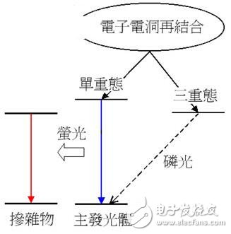
In the process of electron movement, the whole process of electron filling to the hole position is equivalent to the electron obtaining energy (electric energy) and flying away from the original atom, and then being trapped by the hole, and releasing the originally obtained energy (light energy). In this process, if the electron spin (Electron Spin) and the ground state electrons are paired, it is a singlet (Singlet), and the light released is so-called fluorescence (Fluorescence); conversely, if the excited state electron and the ground state electron are self-synchronized Unpolarized and parallel, it is called a triplet, and the light it emits is called Phosphorescence.
Whether in the fluorescent or phosphorescent state, when the state of the electron is returned from the excited high energy level to the steady state low energy level, its energy will be either Light Emission or Heat DissipaTIon (the vibration of the OLED material molecule group). The mode is released, in which part of the photon can be utilized as a display function.
Oled's illumination process can be divided into the following steps: 1. The battery or power supply of the OLED device applies a voltage across the OLED. 2. Current flows from the cathode to the anode and through the organic layer (current refers to the flow of electrons). 3. The cathode outputs electrons to the organic molecular emission layer. 4. The anode absorbs electrons from the organic molecular conduction layer. (This can be considered as the anode outputs holes to the conductive layer, the effect of the two is equal. 5. At the junction of the emissive layer and the conductive layer, electrons will combine with the holes. 6. When the electrons encounter holes, they will fill the holes. (It will fall into an energy level in the atom of the missing electron.) 7. When this process occurs, the electron will release energy in the form of photons. 8. OLED emits light.
Wherein, the color of the light depends on the type of the organic molecules of the emissive layer; the brightness or intensity of the light depends on the magnitude of the applied current. The higher the current, the higher the brightness of the light. OLED molecules rely on the number of pairs of hole electrons received to emit light. A large current means that the number of electrons and holes moving at the same time is large - this is a typical current drive mode.
Product Description
SPD Surge Protective Device,Lightning Surge Protector
Surge Protection Device (SPD)
It is a device used to limiting instant surge voltage and discharge surge current, it at least including a non-linear component.
Surge protective Device Model Selection
With the impact of international information flow, the rapid development of microelectronic science and technology, communication, computer and automatic control technology, make the building start to go for high quality, high functional area, formed a new building style-intelligent building. As inside the intelligent building there are lot of information system, <<Building lightning protection design norm>> GB50057-94(2002 vision)(hereafter brief as <<lightning protection norm>>) put forward the relative requirement to install the surge protective device, to ensure the information system safely and stable running.
SPD essentially is a equipotential connection material, its model selection is according to the different lightning protection area, different lightning electromagnetic pulse critical and different equipotential connection position, decide which kind of SPD used in the area, to achieve the equipotential connection with the common earth electrode. Our statement will based on SPD's maximum discharge current Imax, continuous operating voltage Uc, protection voltage Up, alarm mode etc.
As per << Lightning Protection Norm>> item 6.4.4 stipulation "SPD must can withstand the expected lightning current flow and should confirm to the additional two requirements: the maximum clamp voltage during surge across, capable to extinguish the power frequency follow-on current after lightning current across." That is the value of SPD's max. clamp voltage add its induction voltage of two ends should be same with the system's basic insulation level and the equipment allowed max. surge voltage.
SPD for Power Supply System Series Selection Guide
The installation of SPD at each lightning protection zone, according to the standard of low voltage electrical appearance, make classification of electrical equipment in accordance with the over voltage category, its insulation withstand impulse voltage level can determine the selection of SPD. According to the standard of low voltage electrical appearance, make classification of electrical equipment in accordance with the over voltage category as signal level, loading level, distribution and control level, power supply level. Its insulation withstand impulse voltage level are:1500V,2500V,4000V,6000V. As per to the protected equipment installation position different and the different lightning current of different lightning protection zone, to determine the installation position of SPD for power supply and the break-over capacity.
The installation distance between each level SPD should not more than 10m, the distance between SPD and protected equipment should as short as possible, not more than 10m. If due to limitation of installation position, can't guarantee the installation distance, then need to install decoupling component between each level SPD, make the after class SPD can be protected by the prior class SPD. In the low voltage power supply system, connecting an inductor can achieve the decoupling purpose.
SPD for power supply system specification selection principle
Max. continuous operating voltage: bigger than protected equipment, the system's max. continuous operating voltage.
TT System: Uc≥1.55Uo (Uo is low voltage system to null line voltage)
TN System: Uc≥1.15Uo
IT System: Uc≥1.15Uo(Uo is low voltage system to line voltage)
Voltage Protection Level: less than the insulation withstand impulse voltage of protected equipment
Rated discharge current: determined as per to the lightning situation of the position installed and lightning protection zone.
SP1 Series
Normal Working Conditions
-Altitude not exceed 2000m
-Ambient air temperature:
Normal range: -5ºC~+40ºC
Extend range: -40ºC~+80ºC
-Relative Humidity: 30% - 90% under indoor temperature condition
- At the place without obviously shaking and shock vibration
- Non-explosion danger medium, non-corrosion gas and dust ( including conductive dust)
Classification
-As per Nominal Discharge Current:
5,10,20,30,40,60KA(8/20µs)
- As per Maximum continuous operating voltage:
275V,320V,385V,420V,440V,460V
- As per to poles
1P,1P+N,2P,3P,3P+N,4P
- As per auxiliary functions:
a. With remote signal output ( remote alarm function)
b. Without remote signal output
Selection Principle
- The continuous applied voltage on the two terminals of SPD should not more than the maximum continuous operating voltage Uc value;
- The voltage protection level Up of SPD should less than the maximum impulse withstand voltage of the protected equipment;
- As per to the different earthing system and protection mode to select the specification accordingly;
Product Features
1, built-in over-current overheating, temperature control circuit technology.
2, the module design, easy installation, online replacement.
3, low leakage current, fast response time, low residual voltage.
4, alarm indication device, green (normal) v red (fault).
| Model/Technical Parameters | WR-B60 | WR-B80 | WR-B100 | WR-B120 | WR-B150 |
| Rated Operating Voltage Un (V ~) | 220V 380V | 220V 380V | 220V 380V | 220V 380V | 220V 380V |
| Maximum Continuous Operating Voltage Uc (V ~) kV | 385V 420V | 385V 420V | 385V 420V | 385V 420V | 385V 420V |
| Voltage Protection Level Up (V ~) kV | ≤1.8≤2.2 | ≤2.4≤2.5 | ≤2.5≤3.2 | ≤3.4≤3.7 | ≤4.0≤4.5 |
|
Maximum Discharge Current Imax(8/μ20μs)kA |
60 | 80 | 100 | 120 | 150 |
|
Nominal Discharge Current In(8/μ20μs)kA |
30 | 40 | 60 | 80 | 100 |
| Response Time | <25 | <100 | |||
| L/N(mm²)The Cross Section Of L/N Line | 16,25 | 16,25 | 16,25 | 16,25 | 25,35 |
| PE (mm²)The Cross Section Of PE Line | 16,25 | 25,35 | 25,35 | 25,35 | 35 |
| Fuse or Switch (A) | 63A | 63A | 63A,100A | 63A,100A | 63A,125A |
| The Line Section of Communication and Alarm (mm²) | ≥ 1.5 | ||||
|
Operating Environment-C |
(-40ºC~-+85ºC) | ||||
| Relative humidity 25 ºC | ≤95% | ||||
| installation | Standard Rail35mm | ||||
| Material of Outer Covering | Fiber Glass Reinforced Plastic | ||||
Surge Protector SPD,Surge Protection Device SPD,SPD
Wenzhou Korlen Electric Appliances Co., Ltd. , https://www.zjmoldedcasecircuitbreaker.com