two. The four-channel power amplifier is matched with the electronic two-way pre-amplifier. The power amplifier part is composed of 4 channels-each of the left and right channels has a treble power amplifier and a bass power amplifier. Figures 8 and 9 show the principle diagrams of a high-frequency power amplifier and a low-frequency amplifier for one channel. The other channel is identical.
1. Tweeter Power Amplifier Tweeter power amplifier is mainly composed of three parts: driving stage, driving transformer and current output stage. The driving stage UT1 is composed of the well-known excellent integrated power amplifier LM1875T. Because the quiescent current of LM1875T when the power supply voltage is ± 15V is as high as 50-60mA, and the primary impedance of the driving transformer is about 40Ω, when driving the driving transformer, the maximum output current will not exceed 100mA, so in most cases , LM1875T works in the Class A state, so that it exerts the best performance advantage, let this veteran regain his second youth ... The final audition effect also fully proves this, it is a creation of myself !
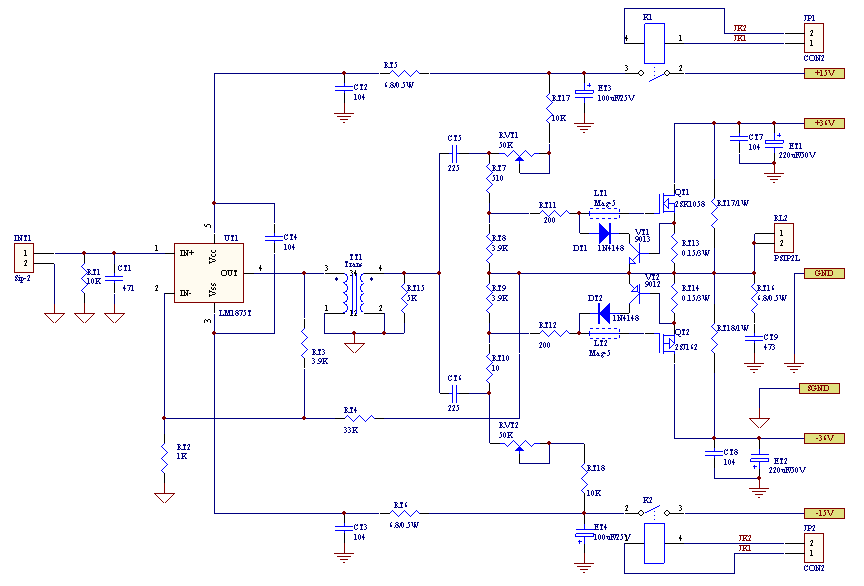
Figure eight
The driving transformer T01 is actually a wide-band step-up transformer with a step-up ratio of 1:12. The fundamental reason for using a transformer here is that the MOSFET power tube is a voltage driving element, and even at a high frequency, only a small driving current is required. A prominent advantage of this method is that the auxiliary power supply of the driving stage is omitted, and a driving voltage of dozens or even hundreds of volts can be generated with a voltage of ± 15V. Push the transformer to use 0.35mm high silicon silicon steel sheet high-quality iron core layered winding, due to the small size, so the simple winding method can get very high performance, the measured frequency response is not worse than 20Hz (0dB)-50kHz (-3dB ), Can fully meet the requirements of full-band Hi-Fi playback.
The current output stages QT1 and QT2 are composed of a pair of Hi-Fi name tubes 2SK1058 / J162 to form a complementary push-pull circuit. RT17, RT18, RT7, RT 8, RT9, RT10 and RVT1, RVT2 constitute the bias circuit of MOSFET. VT1, VT2 are used for current limiting protection of QT1, QT2, and start to operate at about 4A. The secondary of T01 directly drives the two power tubes QT1 and QT2 through the coupling capacitors CT5 and CT6. The other parts are commonly used mature circuits.
It is worth mentioning that this circuit uses the AC-DC dual-loop negative feedback circuit mode. RT3 and RT2 constitute the DC negative feedback loop of LM1875T, while RT4 and RT2 constitute the AC negative feedback loop. According to the theory of automatic control, the transient response of the double-loop negative feedback system is better than that of the single-loop system, so this circuit mode has a better effect on suppressing transient distortion. At the same time, the combination of driving the inductive output of the transformer and the capacitive input of the MOSFET can virtually eliminate the appearance of transient spikes. Therefore, although the conversion rate of the circuit is not very high, and the frequency response is not as wide as the hundreds of kHz bandwidth common to ordinary amplifiers, the sense of hearing is very good.
In addition, the two relays K1 and K2 of the ± 15V power supply of UT1 are controlled by the interface JP1 or JP2 (the two are equivalent) to control whether the tweeter power amplifier works. The connection method of JP1 or JP2 is described later. When K1 and K2 are released, the power tubes QT1 and QT2 lose their bias, and the output midpoint potential shift is likely to cause the speaker protection circuit to malfunction. Therefore, resistors RT17 and RT18 are added to stabilize the midpoint potential.
2. Bass amplifier The schematic diagram of the bass amplifier is shown in Figure 9, which is basically the same as Figure 8, except that the current output stage uses three pairs of MOSFET power tube complementary outputs. Because the treble and bass amplifiers are installed on a PCB, sufficient power supply is required. Therefore, whether it is a ± 15V or ± 37V power connector, a multi-pin parallel connection method is used, as shown in Figure 9 Jv1C, etc. As the tubes connected in parallel with the current level increase, the input capacitance of the MOSFET also increases several times, so the influence on the frequency response cannot be ignored. The measured DC resistance of the driving transformer is about 950Ω. The input capacitance of each K1058 is 600p, and the input capacitance of J162 is 900p. The calculated -3dB open-loop bandwidth is about 38kHz. Because the driving transformer is included in the negative feedback loop, although not carefully calculated, the overall bandwidth is certainly sufficient. The operating current of the current limiting protection part is around 12A.
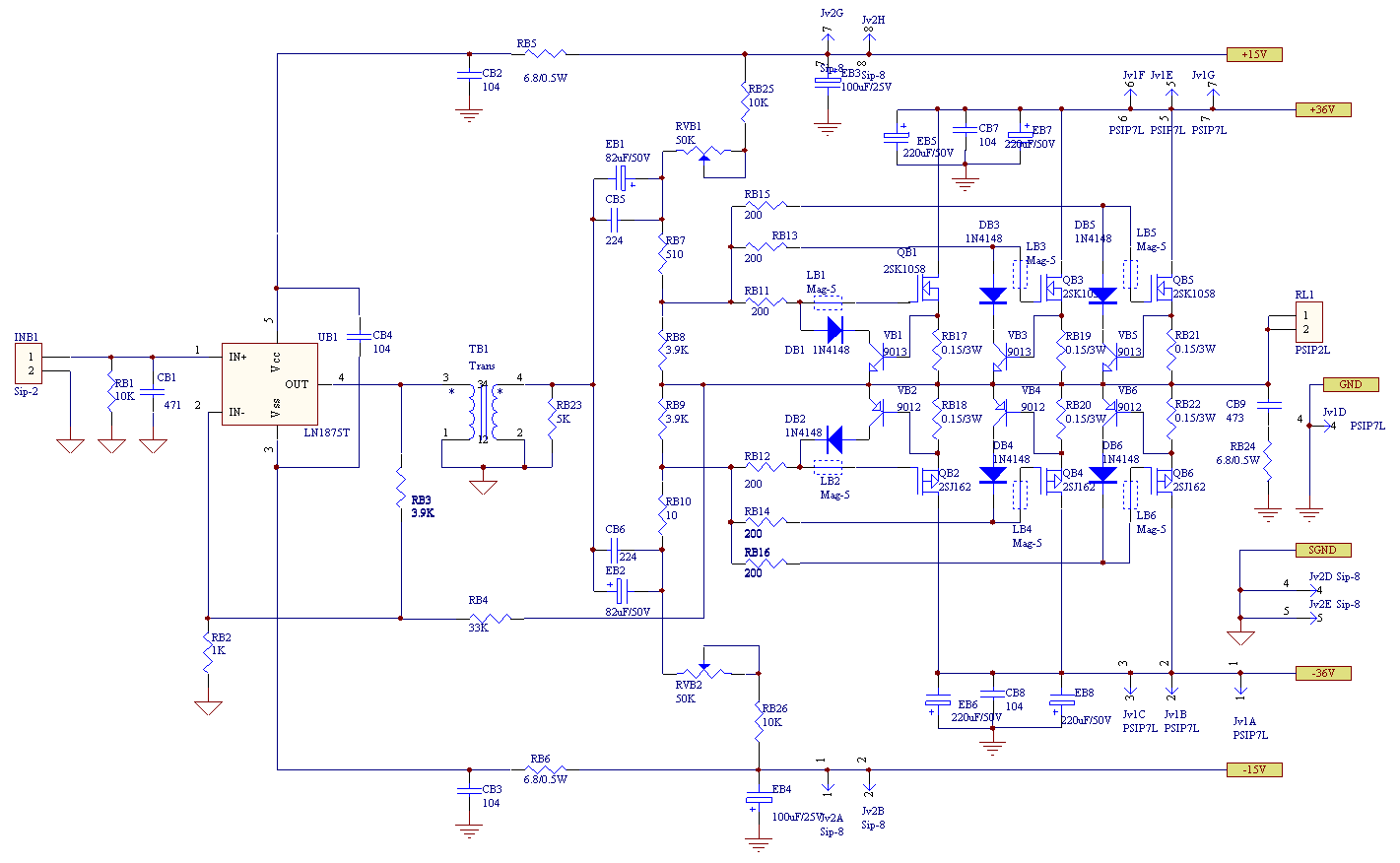
Figure 9
The PCB of the entire power amplifier board is shown in Figure 10, one for each of the left and right channels.
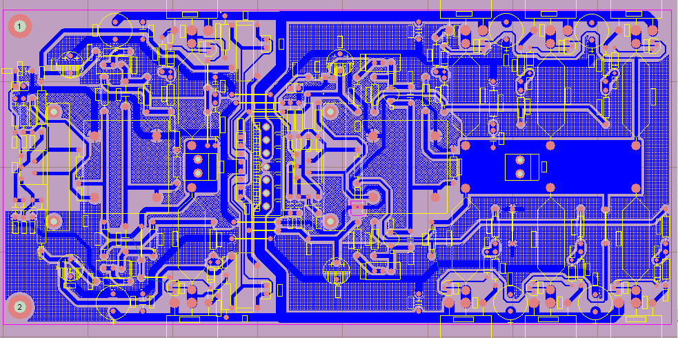
Figure ten
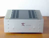
Overall effect:

Follow WeChat

Download Audiophile APP

Follow the audiophile class
related suggestion
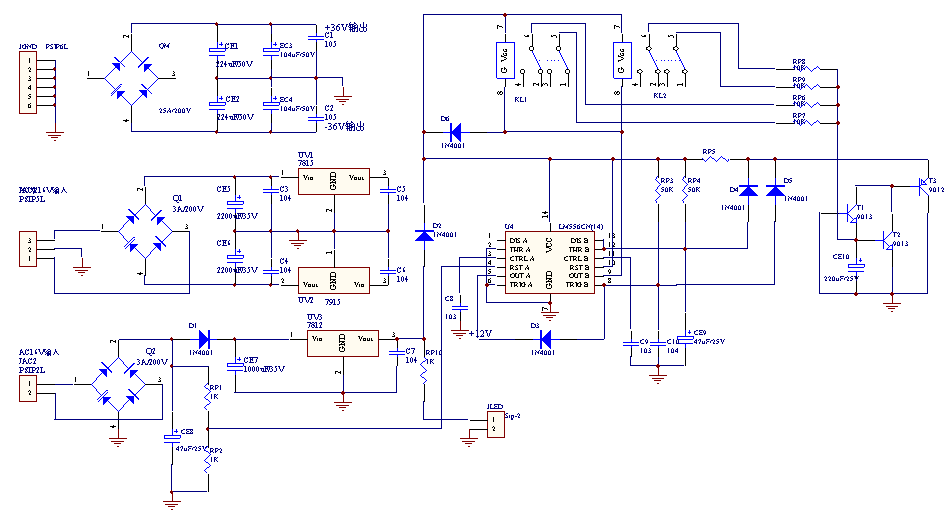
3. Power supply and speaker protection circuit
3. SCM control circuit
