There are mainly two types of three-terminal regulators. One output voltage is fixed, called a fixed output three-terminal regulator, and the other output voltage is adjustable, called an adjustable output three-terminal regulator. The basic principle is the same, all adopt series type voltage stabilizing circuit. In the linear integrated voltage stabilizer, because the three-terminal voltage stabilizer has only three lead-out terminals, it has the advantages of fewer external components, convenient use, stable performance, and low price, so it is widely used.
Because the fixed three-terminal regulator is a fixed three-terminal regulator circuit, its principle is equivalent to a series-type regulator circuit. Examples are shown in the attached drawings.
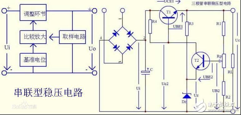
Among them, the voltage divider composed of R1, Rp, and R2 is a sampling circuit, and a part of the voltage UB2 is taken out from the output terminal as the sampling voltage and added to the base of the transistor T2. The voltage regulator tube Dz uses its stable voltage Uz as the reference voltage and is added to the emitter of T2. R3 is the current limiting resistor of the Zener tube. The triode T2 forms a comparative amplifier circuit, which compares and amplifies the sampling voltage UB2 with the reference voltage Uz, and then controls the base potential of the triode T1. It can be seen from the figure that the input voltage Ui is applied to the circuit in which the transistor T1 and the load RL are connected in series. Therefore, the voltage Uo across RL can be adjusted by changing the voltage drop UCE1 between the collectors of T1. In other words, the output voltage Uo of the voltage stabilizing circuit can be adjusted by the transistor T1, so T1 is called a regulator. Since the adjusting element is a transistor and is connected in series with the load in the circuit, it is called a transistor series-type voltage stabilizing circuit. The base bias resistance of resistor R4 and T1 is also the collector load resistance of T2.
When the grid voltage decreases or the load resistance decreases and the output terminal voltage decreases, the sampling voltage UB2 decreases correspondingly, and the T2 base potential decreases. However, because the T2 emitter potential and the stable Uz of the Zener tube remain unchanged, the emitter voltage UBE2 decreases, resulting in a decrease in the collector current of T2 and an increase in the collector potential Uc2. Since the collector of the amplifying tube T2 and the base of the adjusting tube T1 are connected together, the potential of the base of T1 rises, causing the collector current to increase and the tube voltage drop UCE1 to decrease. Because T1 is connected in series with RL, the output voltage Uo is basically unchanged.
In the same way, when the grid voltage or load changes and the output voltage Uo increases, the process of sampling, comparison and amplification, and adjustment will increase the tube voltage drop UCE1 of the regulator tube, which will suppress the increase in the output voltage. The output voltage remains basically unchanged.
Adjust the potentiometer Rp to fine-tune the output voltage.
It can be seen from the figure that the regulator T1 and the load resistor RL form an emitter output circuit, so it has the characteristics of stable output voltage.
In the working process of the series-type regulated power supply circuit, the regulator tube is required to always be in an amplifying state. The current passing through the adjusting tube is equal to the load current, so an appropriate high-power tube must be selected as the adjusting tube, and a heat sink must be installed as required. In order to prevent short-circuit or long-term overload from burning the regulator tube, the DC voltage stabilizer is generally equipped with short-circuit protection and overload protection circuits.
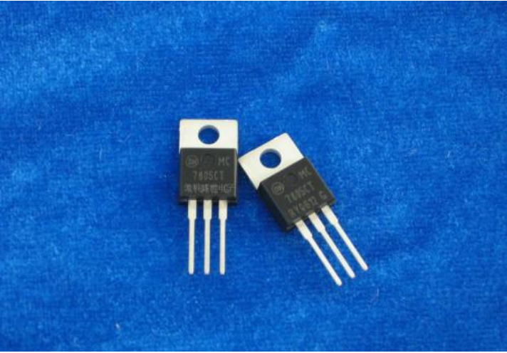
Three-terminal regulator typeThe general products of three-terminal regulators are 78 series (positive power supply) and 79 series (negative power supply). The output voltage is represented by the last two numbers in the specific model, which are 5V, 6V, 8V, 9V, 12V, 15V, 18V , 24V and other grades. The output current is differentiated by adding letters after 78 (or 79). L means 0.1; AM means 0.5A, and no letter means 1.5A. For example, 78L05 means 5V 0.1A.
HuiZhou Superpower Technology Co.,Ltd. , https://www.spchargers.com