The structure diagram of one bit of the 8 bits of P0 port is shown in the figure below:
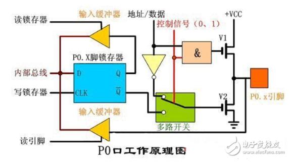
As can be seen from the above figure, the P0 port is composed of a latch, an input buffer, a switch, a NAND gate, an AND gate and a field effect tube drive circuit. Look at the right side of the picture, the label is the icon of the P0.X pin, that is to say, the P0.X pin can be any one of P0.0 to P0.7, that is, there are 8 in the P0 port that are the same as the above picture. Circuit composition.
The role of the pull-up resistor on the MCU portAs the name implies, pull-up means to pull the level high (usually to the power supply), and pull-down means to pull it low (usually to the ground). The pull-up is mainly to improve the current sink driving capability, which is equivalent to borrowing some power from the power supply to the IO port. The pull-down is mainly used when the IO port power is sufficient. In order to protect the IO port, the static level is 0 level.
For different microcontrollers and ports, pull-up resistors have different functions. The most common one is that they cannot be left floating due to internal structure problems. I will use 51 single-chip microcomputer to describe. Take its P0 port as an example. P0 port is an open-collector output, which is an OC gate. This structure does not have the ability to output a high level, which is equivalent to a switch with one end grounded. Output low level 0V, there is no voltage when disconnected, it is a floating state. As for whether to use a pull-up resistor, it depends on the external circuit. If you want to output a high level to control a device, and the device itself does not have a built-in pull-up, you must connect a pull-up resistor yourself, if you want to control a device with a low level , You don’t need to add pull. Generally speaking, when you make a board, you will put a resistance on the P0 port, and 10Kohm will do.
Why should a pull-up resistor be added to the p0 port of the microcontrollerPort P0 has no internal pull-up resistor and is open-drain. No matter how large its drive capability is, it is equivalent to no power supply and needs to be provided by an external circuit. In most cases, a pull-up resistor must be added to port P0.
The internal circuits of port P0 and the other three ports are different, as shown in the figure below:
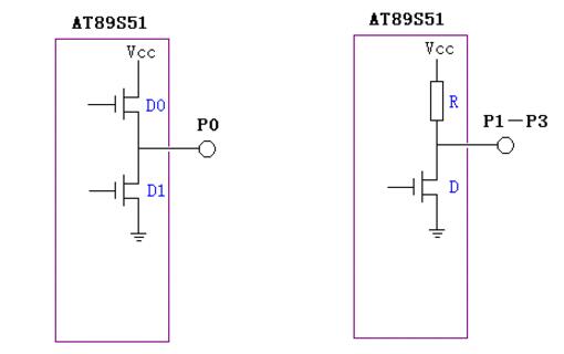
The P0 port is connected between the two transistors D0 and D1, and the upper part of the P1-P3 port is connected to a resistor. The upper transistor D0 of the P0 port will control its conduction and cut-off only when the MOVX instruction is used when entering the expansion memory or expansion bus, and it is cut off when this instruction is not used. In normal times, we use sentences such as: P0_1=0P0_1=1 when the control is the following transistor D1.
Let's first assume that the P1 port is connected to a 74HC373, and take a look at its equivalent diagram
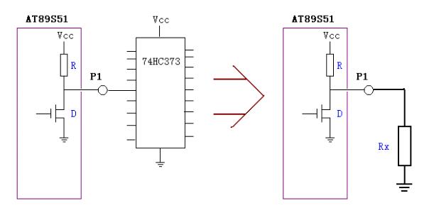
When 74HC373 is connected to the P1 port of AT89S51, it is equal to a load, as shown on the right side of the figure above. Generally speaking, the input impedance of these digital circuits is very large, ranging from a few hundred K to a megaohm, and the resistance R in the P1 port is generally within a few tens of K.
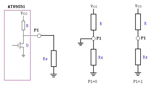
As shown in the figure above, when we issue the command P1=0, the transistor D is turned on. See the equivalent diagram in the middle. At this time, the potential at point P1 is 0.
When the P1=1 command is issued, the transistor D is cut off, see the equivalent diagram on the right, because the resistance of Rx is much larger than that of R, so the potential of P1 is close to the power supply voltage. That is high level.
Let's take a look at the picture when the P0 port is connected to the load
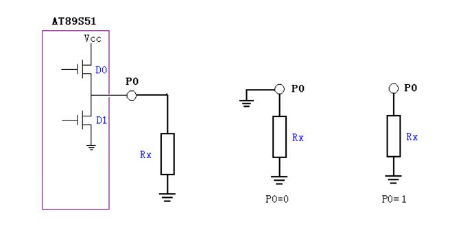
When P0=0, the equivalent diagram is in the middle, the transistor D1 is turned on, and the potential at point P0 is 0.
And when P0=1, the equivalent diagram is on the right, the transistor D1 is off, and the upper transistor D0 is always off, so that the P0 point is equivalent to floating, it is in an unstable state, and the P0 point is RX. The high-impedance input point is easily interfered by the outside world and surrounding circuits, which directly affects the output state of 74HC373. Therefore, a resistor must be added. As shown below
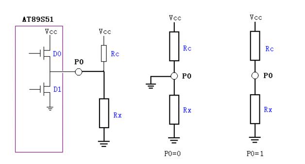
After adding the resistor Rc, the state of the circuit is the same as that of port P1, and this resistor Rc is the pull-up resistor.
But if you just want the P0 port to drive a light-emitting tube, the circuit can be directly simplified as shown in the figure below. The current inside S51 should not exceed 15mA. If the voltage of the LED is 2.2V, the resistance is (5-2.2)÷15=0.18K, which is 180 ohms.
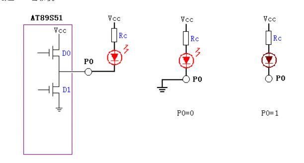
When P0=0, the P0 point is at a low potential, the luminous tube lights up, and the current flowing through D1 is about 15mA.
When P0=1, the P0 point is floating, but the LED and the 180 ohm resistor are both low-impedance components, and the P point potential is high, and there is no output impact, so this circuit is OK
Breaker Rcbo,Rcbo Protection,Leakage Protection Rcbo,Leakage Protection Switch
ZHEJIANG QIANNA ELECTRIC CO.,LTD , https://www.traner-elec.com