Most commonly used electronic devices come with some type of universal serial bus (USB) port. Such ports include Micro, Mini, and Type-A, and all of them can be used with different standards, such as 2.0 or newer 3.1. Compared to these ports, the USB type-c function can be said to have a big leap forward, and the speed is faster and the power transmission performance is better. With this more advanced connector, you can solve all the problems that arise with its predecessor. Type-c handles high-speed data, video, and a lot of power. With these extensions of Type-C, consumers can use the Type-C cable to charge, stream, or transfer data without having to use a variety of cables. Manufacturers basically only need to provide a Type-C connection in their devices to support different uses.
Support multi-communication protocol Type-C to improve device availability
The versatility of Type-C makes the design very complicated, because the extremely simple internal operation of USB is now replaced by more complex embedded components when using connectors, ports, Dongles and hubs. The seemingly simple HDMI to Type-C cable is not easy to design because of the need for an embedded device. There are two major challenges in developing a Type-C solution. The first is to deal with the wide range of power that the port can provide. The second is to avoid communication failures that may occur due to increased support communication standards. When two devices are connected, the Power Delivery (PD) protocol begins to execute.
The program needs to negotiate the amount of power delivered, the power supply, and the power consuming device. Since this communication needs to detect, read and process analog and digital signals, it is necessary to obtain the MCU function through the host connection port, the connection line or the embedded MCU in the Dongles. A failure occurs when the device or host cannot support each other and communication cannot be established. When the signal is detected, the signal is transmitted to the host and further MCU functions are required.
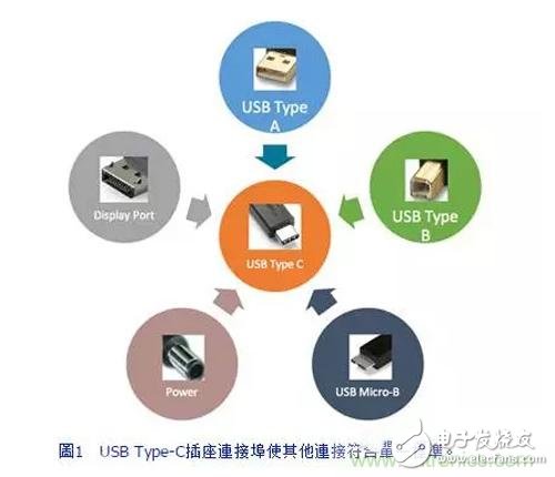
USB Type-C not only reduces the number of cables used, but also ensures smooth collaboration between devices, which brings considerable convenience to users and consumers, but also causes trouble for designers and developers. . Currently, there are many types of USB ports and cables on the market, including Mini, Micro, Type-A, and Type-B. A wide variety of types can be confusing, such as the connection between a mobile phone and a laptop, and the connection of the notebook is different from that of a digital camera. USB Type-C reduces most of the connectivity to a single standard (Figure 1), covering all devices and increasing availability. USB Type-C supports multiple protocols and is backward compatible with USB 2.0. Almost all accessories, such as monitors, headsets, chargers, and keyboards, can communicate with devices such as computers, tablets, and smartphones using USB Type-C.
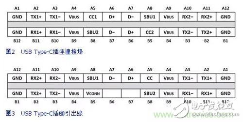
The configuration of the connection port and the connection line is as shown in Fig. 2 and Fig. 3. Since the signal in the socket connection is symmetrically designed, flipping the plug does not cause any problems. USB 3.1 SuperSpeed ​​TX/RX, VBUS, GND, and all other pins are properly connected, regardless of directionality. From the user's point of view, because the Type-C cable can be inserted in either direction, it is an upgraded version of the Type-A port.
The USB Type-C is versatile and easy to use, but adds to the internal complexity of devices using USB Type-C. Although the power capacity is increased, up to 100 W of power can be supplied to charge a high current device, but it also poses a problem for a device that does not require such high power. Power transmission agreements have also emerged. The PD ensures that an appropriate range of power is transmitted or obtained through any connection device.
Host downlink/device uplink connection, both must agree on power
Before discussing the USB Type-C, it is necessary to distinguish between the device, the host, the power supply (power supply), and the power receiver (consumer). The host is not necessarily a power source, so these two terms cannot be used interchangeably. The host initiates all communications and the device responds. In general, the host is a downlink connection (or DFP); the device is an uplink connection (or UFP). If two hosts are connected, the host can act as a dual-purpose port (or DRP), switching between host and device roles. The following example provides an explanation for the above-mentioned rhetoric: when the keyboard is connected to the notebook, the keyboard is a UFP and a consumer, and the notebook is a DFP and a power source.
The initial power transfer protocol between the connected devices is performed through a series of resistors that act as voltage dividers on the CC line when the Type-C plugs are plugged into the socket. Since the CC line in the plug is connected to CC1 or CC2 in the socket, the socket can determine the direction of the plug by measuring the voltage on the CC1 and CC2 lines. The different values ​​of the pull-up resistors convey the amount of current the power supply can provide, while determining what the UFP and DFP are, respectively. Power consuming devices have no way to indicate the amount of current they consume through different pull-down resistor values, but must constantly adjust their load to match the maximum current that the power supply can provide.
In order to be able to read the voltage divider correctly, both devices need to have an analog processing unit, usually in the form of an ADC inside the MCU. The ADC continuously measures the voltage on the CC line to monitor the connection between the plug and the outlet. The MCU, also known as the PD controller, handles the complete physical layer as well as the upper layer protocols and also negotiates the power being transmitted or received. For simple Type-C applications, the power negotiation mechanism can use resistor stop. However, in order to provide a more adaptive design, the device can communicate on the CC line and agree on different settings.
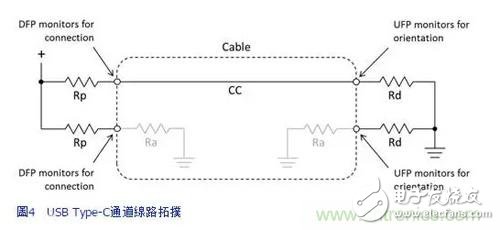
After determining the direction of the plug and the initial power, the device communicates with each other using the CC line (Figure 4). In this way, the device can agree on different power sources and specify a consumer or power source to instantly adjust the power transfer. CC line communication can also be used to inform the type of communication that will be used. As mentioned earlier, the USB Type-C can communicate on high-speed lines, USB 2.0, and so on. The device will notify the lines that can be used by the CC line. But not all devices support all communication protocols.
If the two connected devices do not support each other, a malfunction will occur. For example, if a monitor that can only receive video from the host is connected to a host that cannot support or provide video data, a failure will occur. If this happens, the host still cannot know the failure because the communication cannot be established. In view of this, the USB Type-C standard requires the embedded device or the device end on the monitor as a fault protection device, also called a notification device. The notification device transmits the signal to the host via the USB 2.0 standard on the D+ and D- lines that cannot establish communication. The host then notifies the user that the two devices are not compatible (Figure 5). The notice device will generally be an MCU and may be the same as the PD controller.
Realize old device transfer Dongle plays power negotiation role
If you want users to use older peripherals that do not support USB Type-C, you will need to use a conversion cable or Dongle. There are a few points to explain, the first is a simple USB 2.0 to Type-C. Since USB 2.0 does not support higher speeds and does not require 5V or more of voltage or current on Vbus, the connection line only needs to transfer D+/D-, Vbus and GND to the connector. The more difficult is how to develop Type-C to Type-C cable, convert USB 3.0/1 to Type-C Dongle, or device that requires 5V or more of voltage or current on Vbus.
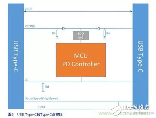
In these cases, Dongle becomes part of the power negotiation between the two devices, requiring the cable or the Dongles to have an embedded PD controller. The PD controller is initially powered by a Vbus or Vconn line set to 5V, and then negotiates with the host to agree on the power supply in the Vbus line. Figure 6 shows an electronically labeled cable assembly, or an EMCA example, that connects two Type-C devices together. The power of the PD controller can be supplied by Vconn1 or Vconn2. EMCA will inform it of the maximum power capacity on the CC line and the power supply will adjust accordingly.
Alternate Mode is an extension of the Type-C interface that allows Display Port, PCIe, or other protocols to use USB 3.1 SuperSpeed ​​lines. When the adapter is connected to a compatible host, it will enter the alternate mode. Dongle, which supports alternative modes, requires additional precautions and embedded devices. Dongle must tell the host if it can enter the alternate mode to avoid no message errors.  
Dongle notifies through the notification device, while the USB Type-C PD standard authorizes any alternative mode accessory to execute the notification device. Figure 6 shows the cable that converts the old video connector to Type-C. If the Type-C device does not support the old video format, the PD controller will notify the notification device and then inform the Type-C device of the error condition.  
More complex than displaying åŸ /Type-C to Type-C is a docking station or hub that must support the charging of many devices. The hub can be a combination of multiple Type-C or Type-A ports, HDMI, PCIe, etc. (Fig. 7). This hub requires multiple embedded devices to successfully support the connected device. The amount of power required for each port is different depending on the connection. With this in mind, each port may require a PD device.
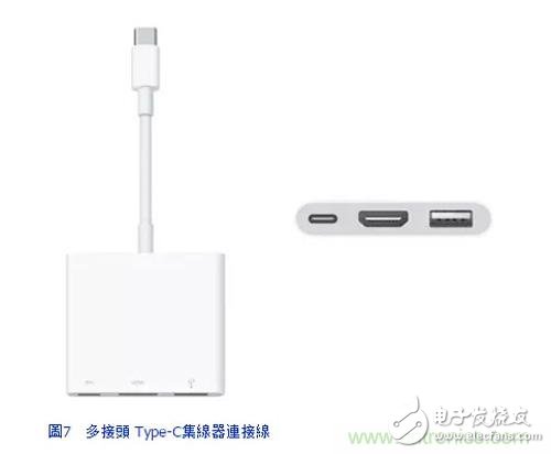
A notification device is required for any video connection (such as display åŸ , VGA or HDMI). In addition, the hub requires a device to control the traffic to the host. This is not much different from the Type-A hub because it avoids collisions on the line and ensures that only one device communicates with the host at a time. Obviously, the design requirements are now more complex and demanding than the previous simple hubs. More complex design tasks do not need to be fully borne by the developer. Silicon Labs provides development boards, PD libraries, signage source code, and sample code for Dongle, docking stations, and device ports. Customers who use these tools when developing new Type-C devices can significantly reduce the time and effort required to develop USB Type-C.
Development board solution simplifies Type-C design
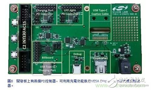
The following is a development board provided by the company that can perform VESA DisplayPort replacement mode adapters using the charging function. A similar development device can provide power, charging, and video transmission through a single port, thereby increasing the functionality of a single Type-C port on the host. There are two PD controllers on the development board, one for each port, and the notification device will work with DisplayPort through the other. The reference design handles switching to alternate mode, charging, notifying the host of the error condition, and ensuring that power is properly transmitted to the display and the host.
Starting with the development board (Figure 8), working on the provided firmware is easier and faster than building a new platform and writing firmware from scratch. Manufacturers and suppliers can thus offer more features for Type-C solutions and are faster than their competitors.
The company's MCU (for example, Busy Bee3) simplifies Type-C design, incorporating PD functionality into a single 3&TImes; 3mm2 single-chip, providing precision oscillators, hardware PD PHY levels, and providing customers with low bill of materials PD solution.
The Universal Bee1 used in the reference design is a single-chip solution that provides noticeability. The integrated regulator, precision oscillator, USB 2.0PHY level, and ±8KV ESD protection on the USB pin enable this 3&TImes;3mm2 device to perform notification functions without the need for external components.
USB Type-C is the standard for future trends. The days of finding the right adapter or cable end from a cable-filled drawer are no longer seen. Looking to the future, when selecting a cable, it is necessary to judge whether the cable is a plug or a socket, and whether the cable can handle a higher amount of power.
Nowadays, there are smart phones, tablets and laptops on the market that only use Type-C ports, and these pioneers are just the beginning. Despite this, Type-C also requires embedded devices and firmware to handle a large number of functions, which also puts tremendous pressure on developers and manufacturers to transfer devices, while Silicon Labs has reference designs, libraries, firmware, and The support team can specifically assist in simplifying the need for Type-C in a wide range of applications.
220Kv Steel Pole,Suspension Steel Pole,220Kv Galvanized Pol,Polygonal Transmission Steel Pole
Jiangsu Baojuhe Science and Technology Co.,Ltd. , https://www.galvanizedsteelpole.com