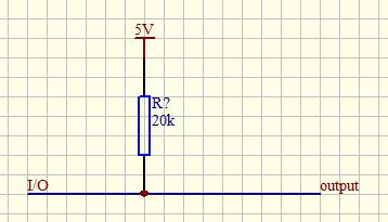
The pull-up is to clamp the uncertain signal to a high level through a resistor, and the resistor also acts as a current limiter. The pull-down is the same, and the uncertain signal is clamped to a low level through a resistor.
The pull-up is the input current to the device, and the pull-down is the output current; the strength is only the difference in the resistance of the pull-up resistor, and there is no strict distinction; it provides current for non-collector (or drain) open-circuit output circuits (such as ordinary gate circuits) The ability to sum the voltage is limited. The function of the pull-up resistor is mainly to output the current channel for the open-collector output circuit.
Generally, when used as a single-key trigger, if the IC itself does not have an internal resistance, in order to maintain the single-key in the non-triggered state or return to the original state after triggering, another resistor must be connected outside the IC.
Digital circuits have three states: high-level, low-level, and high-impedance state. In some applications, high-impedance state is undesirable. You can use pull-up resistors or pull-down resistors to make them in a stable state, depending on the design requirements. !
Generally speaking, it is the IO port, some can be set, some cannot be set, some are built-in, and some need to be connected externally. The output of the IO port is similar to the C of a triode. When C is connected to the power supply through a resistor, This resistor becomes a pull-up resistor, that is, the port is high when it is normal; when C is connected to the ground through a resistor, the resistor is called a pull-down resistor.
The pull-up resistor is used to solve the problem of supplying current when the bus driving capability is insufficient. Generally speaking, the pull-up increases the current, and the pull-down resistor is used to absorb the current.
Why use pull-up resistors in the circuitGenerally, when used as a single-key trigger, if the IC itself does not have an internal resistance, in order to maintain the single-key in the non-triggered state or return to the original state after triggering, another resistor must be connected outside the IC.
Digital circuits have three states: high-level, low-level, and high-impedance state. In some applications, high-impedance state is undesirable. You can use pull-up resistors or pull-down resistors to make them in a stable state, depending on the design requirements. .
The pull-up resistor is used to provide current when the bus driving capability is insufficient. Generally speaking, it is to source current, and the pull-down resistor is used to absorb current. In the long-line transmission, the resistance mismatch can easily cause the reflected wave interference, and the pull-down resistor is resistance matching, which effectively suppresses the reflected wave interference. Resistor series connection is a good way to achieve impedance matching. Usually the order of magnitude of line resistance is in the tens of ohms, if pull-down is added, the power consumption is too large.
Resistor series and pull resistors are both impedance matching methods, but the scope of use is different, depending on the circuit's operating frequency. When the TTL circuit drives the CMOS circuit, if the high level of the TTL circuit output is lower than the lowest high level of the CMOS circuit ( Generally 3.5V). At this time, it is necessary to connect a pull-up resistor to the output terminal of the TTL to increase the value of the output high level. But it should be noted that this method is not recommended because it has two disadvantages:
1. When TTL outputs ground level, the power consumption is large.
2. When the TTL output is high, the pull-up power supply may sink current into the power supply of the TTL circuit, which affects the stability of the system.
For high-speed circuits, excessive pull-up resistors may have smooth edges. When doing input, the pull-up resistor does not absorb current. When outputting, the driving current is the output current of the circuit + the output current of the pull-up channel. The capacitive characteristic of the resistor is very small and can be ignored.
The driving requirements of the lower-level circuit. Take the same pull-up resistor as an example. When the output is high, the switch is turned off. The pull-up resistor should be selected appropriately to be able to provide sufficient current to the downstream circuit. How does the switch tube turn off when the output is high? When the output stage of the CMOS circuit basically pushes and pulls the output ground level, the lower MOSFET turns off and the upper one turns on. The reverse is true when the level is high. This article is only suitable for OC circuits.
Pull-up resistor application principles1. When the TTL circuit drives the CMOS circuit, if the output high level of the TTL circuit is lower than the lowest high level of the CMOS circuit, then it is necessary to connect a pull-up resistor to the output terminal of the TTL to increase the value of the output high level. .
2. The OC gate circuit "must add a pull-up resistor before it can be used".
3. To increase the drive capability of the output pins, pull-up resistors are often used on some single-chip microcomputer pins.
4. On the COMS chip, in order to prevent damage caused by static electricity, the unused pins cannot be left floating. Generally, a pull-up resistor is connected to reduce the input impedance and provide a leakage path.
5. Add pull-up resistors to the pins of the chip to increase the output level, thereby improving the noise tolerance of the chip's input signal and enhancing the anti-interference ability.
6. Improve the anti-electromagnetic interference capability of the bus. If the pin is left floating, it is easier to accept external electromagnetic interference.
7. In the long-line transmission, the resistance mismatch can easily cause the reflected wave interference, and the pull-down resistance is the resistance matching, which effectively suppresses the reflected wave interference.
8. The input pins that are not used in the digital circuit must be connected to a fixed level, and connected to a high level or grounded through a 1k resistor.
Pv Ribbon Intelligent Factory,Solar Intelligent Workshop,Solar Welding Strip Production,Sunlight Solar Bus Bar Production Machinery
Jiangsu Lanhui Intelligent Equipment Technology Co., Ltd , https://www.lanhuisolar.com